
A cold chamber die casting machine pushes externally melted aluminum into a closed steel die with a hydraulically driven plunger at injection pressures that span roughly 7-350 MPa across the high-pressure die casting family, with cold chamber cells most commonly operating in the 2,000-20,000 psi (~14-138 MPa) range at the shot end [S1][S4][S5].
Unlike hot chamber cells, the melt pot, shot sleeve, and injection piston are not immersed in the same bath; molten metal is ladled from a separate holding furnace (typically held between 650°C and 700°C for aluminum) into the shot sleeve, then forced through a pouring hole into the die cavity [S2][S4][S6]. This physical separation of the melt source and the injection hardware is the single defining spec line when you compare a cold chamber machine against other die casting architectures.
Why a Separate Melt Pot Exists: Material and Iron-Pickup Logic
Cold chamber die casting uses an external furnace and ladle to keep iron, copper, and zinc out of contact with molten aluminum at 650-700°C, which is the temperature window where these metals aggressively attack unprotected steel and would shorten gooseneck and plunger life [S4][S6]. Hot chamber cells, by contrast, submerge the gooseneck and plunger in the melt and are restricted to alloys whose melting point is low enough that submerged steel survives; zinc and magnesium fit that window, aluminum does not [S2][S6].
Because aluminum is the most-used metal for the cold chamber process, and because aluminum tolerates higher operating temperatures than the other die cast alloys, the design envelope of a modern cold chamber cell is set by aluminum-grade thermal and corrosion demands, not by zinc or magnesium limits [S3][S5]. The standard architecture for this stack is laid out in the die casting machine reference, which groups the clamping unit, shot end, and hydraulic drive as the three load-bearing sub-assemblies.
The Five Sub-Systems Inside the Machine
Every cold chamber cell is built from five functional sub-systems: a holding/melting furnace, a shot sleeve with pouring hole, a hydraulic plunger and intensifier, a die set clamped between two platens, and an ejector/ejection-side platen [S4][S5]. Holding furnace setpoint is normally 650-700°C for aluminum; shot weight is "higher than 90 grams" per cycle for typical cold chamber parts, with part envelope from "a baseball to a laptop" size class on standard production cells [S3][S4].
The shot sleeve is a horizontal cylinder with a top pouring port; the plunger is a piston pushed by a relatively large hydraulic cylinder whose speed and force profile is synchronized by a controller, with the slow-fill phase protecting the pouring hole and the fast-shot phase building cavity pressure before intensification [S1][S4]. Locking force, not shot pressure, is what sizes a machine, with published ranges from 1 tonne up to 5,000 tonnes and a typical 250-2,400 tonne band for production cells [S4].
Cycle Sequence, Step by Step
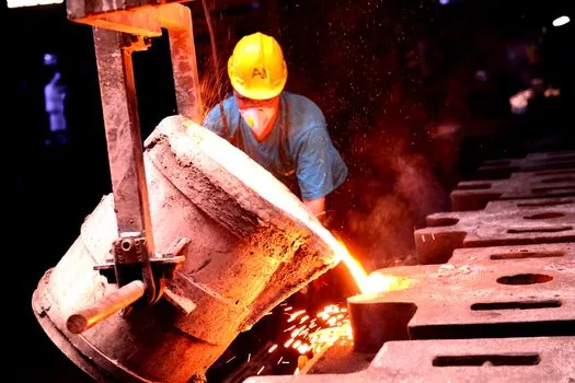
A cold chamber cycle runs in this order: die close and clamp, ladle molten metal into the shot sleeve, slow-shot plunger advance to seal the pouring hole, fast-shot plunger advance to fill the cavity, intensification to set final pressure, dwell under pressure during solidification, die open, ejector pins push the casting out, die close again [S1][S4][S5]. The dwell under pressure is what compensates for shrinkage as the alloy solidifies inside the die.
Cold chamber cycle times are slower than hot chamber, but the trade is worth it for high-melting-point alloys: hot chamber cells can reach roughly 500 parts per hour for small zinc parts, while cold chamber is the only practical route for aluminum structural components where wall integrity, mechanical strength, and temperature resistance matter more than per-shot speed [S4][S5]. For context on how this stacks up against the broader family of high-pressure processes, see the aluminum die casting machine entry.
Injection Pressure, Intensification, and What the Numbers Mean
Cold chamber injection pressure at the plunger most commonly sits in the 2,000-20,000 psi (~14-138 MPa) band, which is a wider and generally higher-pressure window than what a hot chamber zinc cell sees; cavity pressure during intensification is the variable that actually drives part density and minimum wall thickness [S1][S5]. Holding pressure and dwell time are tuned to the alloy's solidification range, not to a single number, and shrinkage is compensated by overpacking during this final phase [S1].
Typical reported shot-end pressure for cold chamber aluminum cells in trade publications is "injection forces exceeding 10,000 psi", with intensified cavity pressures in the 70-140 MPa range on standard production equipment [S1][S4]. These numbers are not interchangeable: shot-end pressure is what the hydraulic cylinder delivers, cavity pressure is what the alloy actually sees after sprue, runner, and gate losses.
What Cold Chamber Is For, and Where It Fails
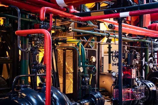
Cold chamber is the right pick when the alloy is aluminum, brass, magnesium, or copper (high-melting-point and/or chemically aggressive toward steel), when shot weight is above roughly 90 g, when parts are large, thin-wall, or structurally loaded, and when high volume amortizes the slower cycle [S3][S5][S6]. For small zinc hardware and high-volume cosmetic parts, hot chamber wins on cycle time, energy, and machine footprint [S2][S6].
Cold chamber is the wrong pick when the alloy is zinc, when the part is a small connector or consumer-electronics bracket, or when cycle time dominates the cost model; for those jobs, a hot chamber cell is the right architecture. Vacuum-assist variants exist for parts where porosity control matters (automotive structural nodes, safety housings) and are covered in the vacuum die casting machine reference.
Comparison: Cold Chamber vs Hot Chamber on the Variables That Matter
On four decision criteria, cold chamber and hot chamber line up as follows. (1) Alloy: cold chamber = aluminum, brass, magnesium, copper; hot chamber = zinc, low-melting magnesium. (2) Typical shot weight: cold chamber above 90 g, hot chamber below ~90 g. (3) Cycle throughput: hot chamber reaches about 500 parts/hour on small zinc parts, cold chamber is slower per shot. (4) Melt pot location: cold chamber uses an external furnace and ladle, hot chamber submerges the gooseneck directly in the melt [S2][S3][S4][S5][S6].
That four-line matrix is the decision tool most buyers actually use. If your alloy, weight, and volume all fall in cold chamber territory, you also need to check shot-end pressure class, locking force (tonnes), platen size, and whether vacuum-assist or squeeze-cast variants are required for porosity targets, as called out in the broader gravity die casting machine and magnesium die casting machine references.
Sourcing, Standards, and What to Verify at Quote

At RFQ, lock down the four numbers that drive price: locking force in tonnes, platen size, shot weight capacity, and maximum injection pressure; confirm the hydraulic versus servo-hydraulic drive, the intensifier type, the die-height and tie-bar clearance, and whether the controller supports process-data logging for PPAP-level traceability [S4][S5].
Also confirm the external holding furnace interface (650-700°C setpoint for aluminum, dosing furnace versus manual ladle), the shot-sleeve material and pre-heat protocol, and the ejector-pin layout matched to your part's draft and undercut plan [S3][S4]. Buyers comparing cell layouts often cross-reference foundry-side auxiliaries like cupola furnace failure modes and prevention and the five-stage structure that underpins every molding line working principle before signing the PO.
Watch for two verifiable signals in 2026: servo-hydraulic and hybrid-electric shot-end retrofits on existing cold chamber cells, and broader adoption of vacuum-assist on structural aluminum nodes, both visible in OEM process-data white papers and at the 2026 Euroguss and Die Casting Congress technical programs.