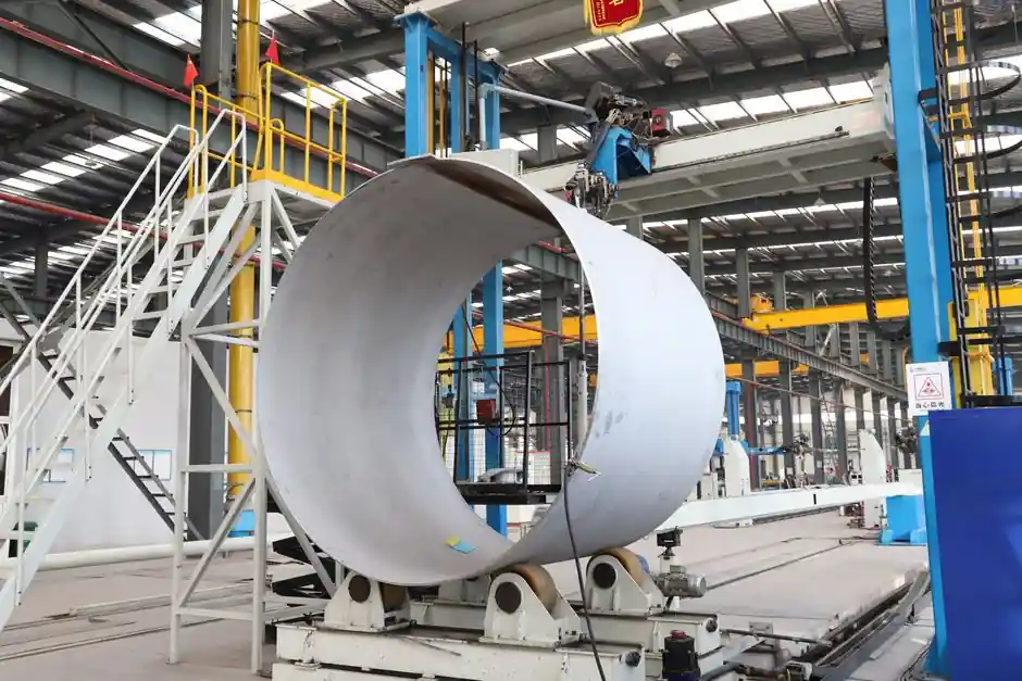
In high-pressure die casting, the shot sleeve is a cold-chamber pressure vessel that holds molten aluminum and feeds it to the die under plunger thrust, making it one of the most thermally and mechanically loaded components on the machine.
The four most common failure modes reported across industry sources are thermal fatigue (heat checking), gross cracking, erosion opposite the pour hole, and piston-to-bore clearance growth; a single mode, or any combination, can take a sleeve out of service well before its design life [S3][S4][S5].
Mechanism #1: Thermal Fatigue and Heat Checking on the Bore
Differential heating of the internal bore, where the inboard surface cycles from cold-start to roughly the liquidus temperature of the alloy shot after shot, drives a compressive-tensile strain field that nucleates a network of fine surface cracks called heat checking [S3].
Heat checking is the dominant damage mode in sleeves built from standard H13 tool steel (W.Nr. 1.2344) when operating temperatures and cycle counts push the material past its tempering stability; the cracks initiate in the nitrided case and propagate into the core, eventually linking into larger fissures that leak molten metal [S3][S4].
Counter-measures verified by commercial sleeve builders are: a minimum 1-1/2 in. (about 38 mm) heavy wall section, vacuum-furnace heat treatment to 46-48 Rc with a minimum of two tempers at 1100 °F (about 593 °C), and an internal gas-nitride case of 0.010-0.012 in. (about 0.25-0.30 mm) depth to put the high-strain surface into compression [S3].
Mechanism #2: Pour-Hole Washout and Erosion
Most premature sleeve failures in production HPDC are localized to the bore directly opposite the pour hole, where the high-velocity metal stream entering the chamber scours the nitrided case; Castool reports that this pour-hole washout is the single most common reason sleeves are pulled even when the rest of the bore is still mechanically sound [S4].
Industry case studies on brass HPDC shot sleeves attribute similar localized erosion and downstream thermal-fatigue cracking to repeated high-pressure compression of the melt during injection, which adds a mechanical loading component on top of the thermal cycle [S2].
Mitigation rests on two levers: derating the pour-stream velocity at the ladle-to-sleeve interface, and applying a hot-yield upgrade to the inner bore through a weld overlay of W.Nr. 1.2367, which keeps higher hot strength and heat-check resistance than the underlying 1.2344 base, then re-nitriding to spec [S4].
Mechanism #3: Gross Cracking and Sleeve Distortion

Gross or large-scale cracking tends to follow heat-check networks that have run for enough cycles to coalesce, but it can also be initiated by bore distortion when the inner wall temperature and the outer wall temperature diverge enough to bow the cross-section [S3].
For aluminum HPDC, the cold-chamber sleeve sees inner-wall surface temperatures well above the as-tempered temperature of the tool steel during steady-state operation, so distortion under thermal gradient is a real and measurable contributor, not a theoretical one [S8].
The distortion problem is addressed mechanically with water or hot-oil cooling circuits integrated into the sleeve body, and metallurgically with the 46-48 Rc / 1100 °F double-temper schedule that retains hot yield at the bore surface [S3][S8].
Mechanism #4: Piston-to-Bore Clearance Growth
As the bore wears, the diametral clearance between the plunger tip and the inner sleeve wall grows past the allowable value; once clearance is exceeded, metal flash bypasses the plunger, accelerating both sleeve and tip wear and changing the fill profile of the shot [S5].
Peer-reviewed analysis on brass HPDC sleeves has documented that this clearance growth, combined with thermal cycling, is a leading contributor to premature sleeve retirement, with the piston-side wear band often exceeding the bulk bore wear rate by a measurable margin [S2][S5].
Acceptable plunger-to-sleeve clearance is process-specific, but the practical rule of thumb published by reconditioning specialists is to scrap or re-bore a sleeve as soon as diametral growth exceeds the design tolerance set for the plunger tip in use, rather than waiting for visible flash at the parting line [S5][S6].
Prevention: Material, Hardness, and Nitride Engineering Compared
Three process options are commonly used to extend sleeve life, and the right choice depends on alloy, cycle time, and shot weight: standard H13 (W.Nr. 1.2344) through-hardened to 46-48 Rc, the same H13 baseline with a deeper gas-nitride case to 0.010-0.012 in., and a hybrid approach that welds W.Nr. 1.2367 into the worn bore of a used sleeve before re-nitriding [S3][S4].
On hot yield strength and heat-check resistance, W.Nr. 1.2367 outperforms the standard 1.2344 baseline, and the 1.2367 chemistry also accepts a more aggressive nitride that delivers higher surface hardness and better temperature resistance; the cost is a re-bore process, not a new sleeve, with up to 1.5 mm of base material removed before a 3 mm 1.2367 overlay is welded in place [S4].
Standard H13 through-hardened sleeves remain the lowest-cost choice for low-to-medium shot-count applications, while the nitrided H13 variant is the workhorse for general aluminum HPDC; the 1.2367 bore-weld repair is the highest-end option for foundries running high-mix, high-cycle production where a new sleeve would otherwise scrap the entire shot-end assembly [S3][S4].
Repair vs. Replace: When Bore Welding Pays Back
A shot sleeve is a candidate for bore-weld repair, not scrap, when the failure is a localized washout under the pour hole and the outer body has no through-wall cracks, because the 1.2367 overlay restores the wear surface while preserving the mechanical integrity of the original forging [S4].
Foundries that pair bore-weld repair with preventive cooling and a tightened ladle-pour practice typically run sleeves to two to three times the as-new life on common aluminum components, though the exact multiplier is workload-dependent and not standardized across the industry [S4][S6].
Operators evaluating a repair path should specify a 3 RMS internal surface finish after final honing, confirm nitride depth on the rebuilt bore, and reject any incoming sleeve that shows through-wall cracks or distortion beyond the maker's published dimensional envelope [S4].
Operational Signals to Track on the Shop Floor

Track the diametral clearance between plunger tip and bore at every planned tool-room inspection, the depth of any heat-check network visible at the bore, and the nitride case depth at the pour-hole band, because all three are leading indicators of end-of-life and all three are measurable without dismantling the cold-chamber assembly [S3][S5].
Also monitor cooling-water inlet temperature and flow at the sleeve body, because a 10-20 °C drift in the cooling circuit correlates with measurable bore distortion on H13 cold-chamber sleeves running steady-state aluminum shots, and the failure usually shows up first as a gain in diametral ovality rather than a crack [S8].
Foundries that formalize these inspections inside their preventive-maintenance system typically catch the failure mode before the sleeve welds itself to the cold-chamber, which is the worst-case outcome and the one that takes the machine down for a hot-bench extraction [S4][S6]. For a deeper dive on spare-parts selection and consumables that pair with this maintenance plan, see the shot sleeve spare parts spec map.
Detailed specification references: shot blasting machine, and construction machinery and equipment.