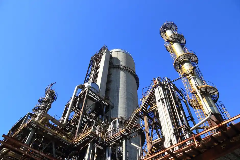
A modern compressed air system is a stack of eight functional blocks: intake filter, compressor, aftercooler, receiver, dryer, line filter, condensate drain, and distribution network, with downstream pneumatic tooling, air impact wrench stations, and process actuators as the load side.
Upstream supply is dominated by screw and centrifugal compressor OEMs, refrigerated and desiccant dryer makers, and filter houses that publish ISO 8573-1:2010 purity classes. Downstream, demand is anchored in pneumatic conveyor lines, paint spray booths, food and pharma packaging, and instrument air for air solenoid valve manifolds.
Upstream component map: compressors, treatment, and storage
The upstream bill of materials breaks into four sub-systems, each with a distinct supplier base. Compression itself splits between oil-injected rotary screw (7 bar g to 13 bar g, the workhorse of discrete manufacturing), oil-free screw and centrifugal (8 bar g to 40 bar g, required for food, pharma, and electronics), and reciprocating piston (up to 30 bar g, common in small shops and as a backup unit) [S2][S3]. Air treatment is the most fragmented layer: refrigerated dryers deliver a +3 degrees Celsius pressure dewpoint for general plant air, desiccant dryers reach -40 degrees Celsius or -70 degrees Celsius pressure dewpoint for outdoor and instrument air, and membrane dryers suit low-flow, low-maintenance duties [S2].
Storage and filtration tie the chain together. Compressed air receivers are sized at roughly 1 gallon per cfm for short-cycle loads and up to 3-4 gallons per cfm for cyclic demand smoothing; water-cooled and air-cooled aftercoolers (HD and TD series at Atlas Copco) drop discharge air within 10 degrees Celsius of ambient before it hits the receiver [S2][S3]. Festo specifies that planning air preparation from the design stage, in line with ISO 8573-1:2010, prevents malfunctions in downstream pneumatic components and extends service life [S4].
Downstream demand map: where the cubic meters go
Downward of the air receiver, the same kilogram of air splits into very different duty cycles. Discrete manufacturing uses roughly 60-70 percent of industrial compressed air for actuators, blow-off, and pneumatic tool drive; process industries (chemicals, food, pharma) divert a larger share to agitation, pneumatic conveying, and instrument air. Within the conveying slice, the Pneumatic Conveyor Selection: Spec Map and Decision Rules reference frames dense-phase versus dilute-phase transport as a 1.5-3.0 bar g pressure window selection, which is why plant air receivers are commonly pre-sized at 10-15 bar g even when distribution runs at 7 bar g. [S2]
Filtration is the second downstream pivot. ISO 8573-1:2010 defines solid particulate, water, and oil classes from 0 to 9, and most paint and pharmaceutical lines run Class 1.4.1 or better, which forces upstream coalescing filters, activated carbon stages, and silicone-free construction. Atlas Copco's silicone-free filter line is explicitly positioned for coating, automotive paint, and white-room use where silicone carryover causes fish-eyes and adhesion failure [S2].
Selection criteria: pressure class, purity, and sequencer logic
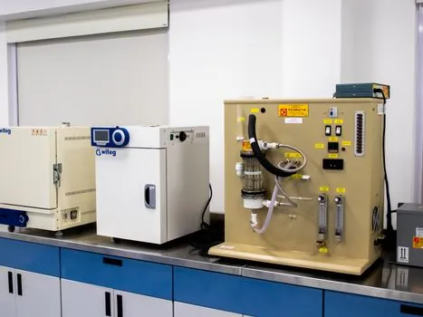
Specifying a compressed air system in 2026-08 means locking down three parameters before choosing hardware: required pressure class, ISO 8573-1:2010 purity class, and load profile. Plant air typically runs 7 bar g to 8 bar g; instrument air for air solenoid valve banks and analytical instruments is held at 8 bar g to 10 bar g with a -40 degrees Celsius pressure dewpoint; PET blow molding and high-pressure pneumatic conveying push distribution pressure to 30 bar g to 40 bar g using oil-free boosters [S2][S3].
On the control side, multi-compressor sequencers are now standard rather than optional. CompAir's SmartAir Master sequences machines across a common manifold to keep combined capacity matched to site demand, with a graphical sequencer interface designed for operator convenience and ease of installation [S1]. The economic case is straightforward: unloaded or idling compressors draw 25-30 percent of full-load power, so trimming one machine off the line under light load recovers kWh proportional to the per-machine specific power, which is typically 6-8 kW per 100 cfm delivered for fixed-speed oil-injected screw units.
Comparison: dryer types, compressor types, and filtration tiers
Side-by-side, the three dryer technologies split cleanly on dewpoint, energy, and maintenance: refrigerated dryers hit a +3 degrees Celsius pressure dewpoint at the lowest capital and operating cost, desiccant dryers with heated purge reach -40 degrees Celsius pressure dewpoint at 2-3x the kWh per cfm, and membrane dryers deliver a -20 degrees Celsius to -40 degrees Celsius pressure dewpoint with no electricity but a steady 15-20 percent purge loss [S2]. Compressors compare on oil carryover, sound, and turndown: oil-injected screw is cheapest per cfm but needs downstream coalescing, oil-free screw and centrifugal hit ISO 8573-1 Class 0 oil by design, and piston units are favored for intermittent high-pressure duty up to 30 bar g.
Filtration tiers are equally tiered. The general-purpose line is rated to Class 2.7.2 (particulate, water, oil), the high-efficiency line to Class 1.4.1, and the silicone-free activated-carbon line to Class 1.4.1 with zero silicone carryover, which is the entry ticket for paint and pharma lines. Reference comparison reading on filter makers and price bands is consolidated in the Industrial filter suppliers map 2026: manufacturers, price bands, and selection guide roundup.
Use cases and supply chain signals 2026
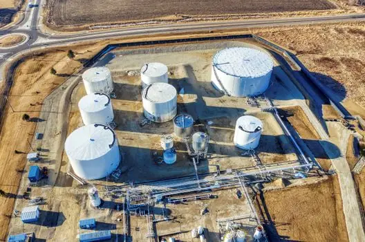
Three end-use profiles dominate 2026 buying. First, automotive paint shops specifying silicone-free filtration and Class 1.4.1 air, with redundant compressor trains and a desiccant dryer with -40 degrees Celsius pressure dewpoint ahead of the distribution ring. Second, food and pharma packaging running oil-free screw or centrifugal compression paired with refrigerated dryers and sterile filtration, often on a Class 0 oil-rated chain. Third, bulk-material handlers running dense-phase pneumatic conveying at 2-4 bar g from dedicated oil-free boosters, with the receiver sized for 30-60 second buffer at peak conveying rate [S2][S3].
The supply-side signal through 2026-08 is redundancy and zone segmentation. Multi-compressor rooms are being split into a base-load machine, a trim machine, and a standby, with the sequencer arbitrating to keep turndown above 70 percent on every running unit. A practical implementation pattern is documented in the Compressed Air Supply Chain 2026: Redundancy, Zone Management, Filtration Tiers field reference, which is consistent with the sequencer-based logic CompAir publishes for SmartAir Master installations [S1].
Limitations, failure modes, and standards
The dominant failure modes in a compressed air system are not compressor failures; they are treatment failures. A fouled intake filter costs 1-2 percent specific power per 250 mm water column of pressure drop, a saturated desiccant bed sends wet air downstream, and a failed condensate drain discharges oil-contaminated water. Festo's design-stage guidance, which treats air preparation as a planning input rather than a retrofit, is the cheapest way to avoid these failure modes [S4].
On the standards side, ISO 8573-1:2010 is the reference for purity classes across solid particulate, water, and oil, and it is the document every filter and dryer datasheet cites. Compressor intake and discharge design leans on ISO 1217 for full-load performance, and plant air receivers are built to ASME BPVC Section VIII for unfired pressure vessels. For explosion-risk sites, compressed air equipment in classified areas falls under the IEC 60079 series and the ATEX 2014/34/EU directive, with the equipment group and temperature class pinned to the gas or dust group in service [S2][S3][S4].
Trackable signals over the next buying cycle: (a) sequencer-led retrofit quotes at sites still running a single fixed-speed compressor above 75 percent average load, where a 2-machine sequenced pair typically cuts specific power by 10-15 percent; (b) silicone-free filter upgrade orders tied to paint-shop and pharma expansions; (c) desiccant dryer replacement cycles at -40 degrees Celsius pressure dewpoint sites where the tower has crossed roughly 3-5 years in service, depending on inlet temperature and load factor [S1][S2][S4].