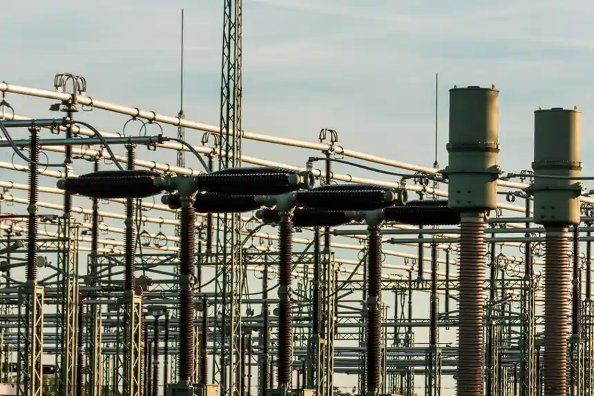
Select a conductor-bar system when the crane requires uninterrupted runway power, higher-current delivery or operation in low-headroom areas; select a festoon when flexible cables, auxiliary hoses and accessible loop maintenance are priorities.
Both systems power electric overhead bridge cranes, but they serve different movement zones: conductor bars commonly follow the runway, while festoon cables can cross the bridge to feed the hoist trolley.
Conductor Bars or Festoon Cables: Core Selection Criteria
Conductor bars use a sliding shoe collector system to transfer power to a crane and hoist [S4]. A typical insulated installation includes the bar, incoming power feed, collector, support brackets, hangers, end covers and an anchor clamp that accommodates thermal expansion and contraction [S4].
A festoon carries flat or round cable on trolleys running in C-track, square rail or along an I-beam. The cable loops spread or contract as the crane or trolley travels, so the route must preserve the designed bend geometry and hanging clearance [S4][S5].
The principal decision is electrical duty against serviceability. Conductor bars favor continuous collection, current capacity and compact routing. Festoons favor flexible cable construction, auxiliary hose support and easier identification of individual conductors. The choice also depends on available space, crane configuration, travel pattern, duty cycle and environment [S3][S4].
Conductor-Bar Performance and Installation Constraints
Conductor-bar systems suit indoor and outdoor cranes and can support more than one bridge operating on the same runway [S4]. They are particularly suitable for low-headroom installations where suspended cables would obstruct the required envelope, and they accommodate curved routes or track switches [S4].
Runway extensions are comparatively straightforward because conductor bars can be connected, making the method practical for future expansion and interlocking crane systems [S4]. Finger-safe enclosed bar is identified as a preferred option for new crane and industrial moving-power applications, alongside C-track festoon systems [S2].
The main service liability is collector wear. Sliding shoes can require inspection, service or replacement depending on operating severity [S4]. Sparking or heat damage requires attention to collector contact, joint condition and bar alignment rather than immediate replacement of the complete supply [S5]. Anchor clamps, covers and supports must also be checked because they control safe routing and thermal movement [S4][S5].
Festoon Cable Capacity, Flexibility and Failure Modes
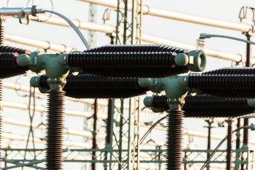
Specified C-track and square-track festoon packages use 4, 8, 12, 16 or 24 conductors, with conductor sizes from 000 AWG to 16 AWG. The annealed-copper conductors have color-coded jackets rated for UV, ozone, water, oil and weather exposure over -40°C to 105°C [S2].
Typical 12 or 14-gauge C-track construction uses galvanized or stainless steel, with factory curves available at 1.2, 1.5, 1.8 and 2.1 m radii; the minimum custom bend radius is 1.02 m [S2]. Heavy-duty aluminum track can be formed to a minimum 0.91 m radius, and its ball-bearing trolley saddles support up to 150 lb of cable at travel speeds up to 250 ft/min [S2].
A festoon failure can require replacement of the affected cable run rather than a single collector shoe. A damaged or worn jacket, flattened conductor, twisted cable, distorted track, seized roller or rubbing support point can interrupt power or control [S5][S7]. Inspect the complete cable path over the approved travel range, including loop collection, hanging clearance, end stops, buffers and damping components [S5].
Direct Comparison by Duty, Access and Maintenance
On current delivery, conductor bars have the advantage because their sliding-contact system can supply higher amperage than alternative moving-power arrangements [S4]. Conductor bars are suitable for low-headroom applications and support runway extensions and interlocking systems [S4]. Their recurring wear point is the collector contact [S5].
On flexibility and auxiliary services, festoons are stronger because the track can carry flat or round power cable and air hoses, including systems with 4 to 24 conductors [S2]. They also permit pre-assembled, wired packages with control-box trolleys, pendant stations and plug-and-play hardware [S2]. Their recurring failure mode involves cable movement, loop clearance and trolley condition rather than bar contact [S5].
On outdoor exposure, neither method is automatically excluded. Specified festoon jackets are rated from -40°C to 105°C and resist UV, ozone, water, oil and weather [S2]. Conductor bars can also be used outdoors, but the collector, joint, cover and grounding arrangements remain critical [S4].
Choose conductor bars for a long-travel runway, multiple bridges, high duty, low headroom or future extension. Choose festoons for a shorter or more complex bridge route, mobile auxiliary services, hose support and access to a replaceable cable package. A hybrid layout is engineering-valid: runway conductor bars with a bridge festoon is a documented arrangement [S5].
Application Fit and Excluded Installations
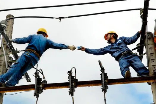
Conductor bars fit continuous-runway cranes, shared runways, low-headroom buildings and routes requiring curves or track switches [S4]. Festoons fit bridges and monorails where the cable must flex through a defined travel cycle and where operators can inspect or service the loops. Both can also form part of a gantry crane power system.
Festoons are less attractive where suspended cable would intrude into the working envelope, where a damaged run must be replaced rapidly, or where continuous collector contact is more important than cable flexibility. A festoon is not automatically unsuitable for high-speed or heavy-duty service, but the track, trolley, cable and curve radius must be selected for those conditions [S2][S5].
Conductor bars should not be used where an explosion-proof crane is required, and the cited application guidance excludes them for powering transfer carts [S4]. For a new crane, specify the electrification system early because surrounding space and support requirements affect bridge, runway and electrical design [S3].
Installation, Inspection and Sourcing Discipline
Design the system against ANSI ECMA 35, Electrification Systems for Electric Overhead Traveling Cranes, which covers minimum requirements and guidance for AC and DC electrification used on overhead electric cranes, monorails, gantry traveling cranes and workstation cranes [S3]. Supplier documentation should also identify conductor count, gauge, voltage, amperage, insulation, track material, bend radius, trolley loading, speed, grounding and enclosure arrangement.
Before inspection, isolate the relevant supply, prevent unintended motion and have a qualified person verify absence of voltage. An emergency-stop or pendant stop is not electrical isolation. Stored energy in a spring-driven reel must also be controlled, and guards must be restored before return to service [S5].
For maintenance, record the crane position, active motion and whether the fault occurs during travel or while stationary. For conductor bars, inspect collectors, joints and covers; for festoons, inspect track, trolleys, supports, jackets, tow ropes and end stops; for reels, inspect cable path, winding and drive type [S5].
Before procurement, freeze the travel distance, trolley load, speed, duty cycle, number of conductors, auxiliary hoses, ambient exposure, headroom, curve radii, collector loading and future runway extension. Confirm that the selected system has the required current rating and that maintenance access exists for shoes or cable loops. These are the trackable signals for a defensible selection: verified duty data, completed route geometry and documented inspection access.