
Process control and instrumentation connectors split cleanly into two families: electrical signal/power interconnects and instrumentation pipe/thread conversion fittings, and the two are specified with almost no overlap in mind.
On the electrical side, spring-style and bayonet industrial circulars typically cover 2 to 26 pin counts [S1]. On the fluid side, ISO conversion fittings and instrument pipe fittings are made from bar stock and forgings per applicable ASTM specifications, in stainless steel and brass as standard [S2]. Specifying across both families is the daily work of an instrument engineer building a process control loop, and this article maps the decision criteria that matter.
Two Families, Two Spec Languages
Electrical connectors for process control and instrumentation are spec'd by contact count, current, voltage, sealing, and mating cycle. The TE/Deutsch IMC series, for example, ships in two shell sizes and seven contact configurations ranging from 2-way through 12-way, with #16, #20, and #22 contact sizes for solid, stamped-and-formed, and PCB tail terminations [S3]. The 100-series is rated 7.5 A on 2- and 3-way layouts and 5 A on 4-way; the 200-series is rated 13 A on 2-way, 7.5 A on 5- and 7-way, and 5 A on 12-way, with insulation resistance of 1000 MΩ and voltage rating up to 1000 Vac (rms) [S3].
Instrumentation pipe fittings, by contrast, are specified by thread form (NPT vs ISO), pressure class, material, and configuration (straight, elbow, tee). Parker Catalog 4260 lists both ISO conversion fittings, designed to bridge NPT and ISO thread configurations using either thread sealant or peripheral face seals, and instrument pipe fittings built as leak-free connections for process, power, instrumentation, and general industrial use [S2].
Selection Criteria for Electrical Connectors
Four criteria dominate electrical connector selection for instrumentation: contact density, current per contact, environmental sealing, and temperature range. The IMC part numbering itself encodes these: IMC16-2002X is a 100-series 2-way inline plug with #20 contacts, while IMC26-1602X is a 200-series 2-way inline plug with #16 contacts rated for 13 A [S3].
Sealing is non-negotiable in process plants: the IMC series is sealed to IP67 against dust and moisture, with a bayonet-type lock coupling, Ultem composite shell, and UL94 Class V-0 flammability rating [S3]. Operating temperature spans -55°C to +175°C, with the 175°C upper limit defined as the maximum internal hot spot from combined ambient and I²R self-heating, a limit an engineer should derate against, not drive to [S3]. A bayonet lock and IP67 seal are the practical minimum for field-mounted lamps and light fittings and sensor harnesses exposed to wash-down or outdoor service.
Selection Criteria for Instrumentation Pipe Fittings
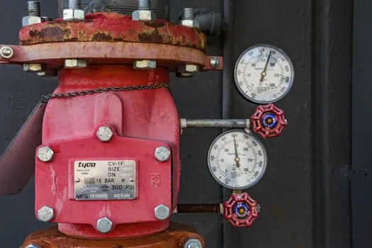
For the fluid side, three criteria matter: thread standard, material, and whether the joint seals on the threads (with sealant) or on a face peripheral seal. Parker ISO conversion fittings are designed for both modes, with straight fittings cut from ASTM bar stock and shaped fittings machined from close-grain forgings [S2]. Standard catalog material is stainless steel or brass, with other alloys available through a special-order quick-response path.
Engineers specifying dual-standard plants (North American NPT + European ISO instrumentation) should use conversion fittings, not field-adapted adapters, to keep thread form, pressure class, and material traceability on a single datasheet. The same logic applies to skid builders integrating equipment from multiple regions, where one wrong adapter can defeat the process calibration trace on a pressure tap.
Comparison: Electrical Circular vs Instrumentation Pipe Fitting
Side by side on the criteria an instrument engineer actually writes on a datasheet:
- Primary function: electrical signal/power transfer (circular) vs fluid/gas line connection (pipe fitting) [S2][S3].
- Key spec axes: contact count, amps, Vac, IP code, mating cycles vs thread form, pressure class, material, seal type (thread vs face) [S2][S3].
- Materials: Ultem composite shell with gold-plated copper alloy contacts (electrical) vs stainless steel and brass to ASTM bar stock (fluid) [S2][S3].
- Sealing standard: IP67 dust and moisture (electrical) vs thread sealant or peripheral face seal (fluid) [S2][S3].
- Temperature window: -55°C to +175°C for the IMC electrical series; pipe fittings are governed by material and pressure-temperature derating per the catalog [S2][S3].
Who This Is For, and Who It Is Not For
Multi-pin industrial circulars in the 2-26 pin range suit instrumentation and process control systems, test equipment, industrial sensors, and medical diagnostic gear that need compact, sealed, often wash-down-tolerant interconnects [S1][S3]. ISO conversion fittings suit plants, skid builders, and EPCs integrating NPT and ISO instrument tubing on the same process line [S2].
These are not the right choices for high-pin-count data backplanes (use rectangular industrial I/O instead), for power distribution above the catalog's voltage/current ratings, or for any fluid joint that needs a third-party-certified fire-safe rating beyond the catalog's standard material set. The pipe fittings described are not a substitute for a multifunction process calibrator connection kit, which has its own sealing and traceability rules.
Standards, Sourcing, and Failure Modes
UL recognition, UL94 Class V-0, and IP67 are the primary compliance marks on the IMC series as published [S3]. On the fluid side, Parker Catalog 4260 ties material to applicable ASTM bar stock and forging specifications rather than to a single named fitting standard, and the catalog's own user-responsibility warning puts the burden of system performance verification squarely on the specifier [S2].
The most common failure mode in the field is seal stack-up: mixing thread-seal and face-seal connections across an instrument manifold without documenting which is which. Second is contact underspec: a 5 A contact in a 13 A service will derate thermally until the 175°C internal hot-spot limit is hit, then open. Both failure modes trace back to incomplete datasheet review, not to the connector itself. The upstream lesson for v process line builders is that connector and fitting choice should be locked at P&ID stage, not at panel build.
For a deeper look at the cost-side tradeoffs that drive connector and wire selection across a 2026 production line, see this cable and wire manufacturing cost breakdown. Where panel builders are also sizing contactors downstream of the same I/O, the contactor duty-category and 1.25x rule guide pairs naturally with the current-rating columns in connector datasheets. For a sensor-stack view of where these connectors actually land in a modernized plant, the Industry 4.0 sensor stack retrofit map is a useful cross-reference.