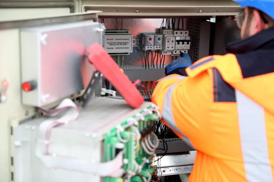
An electromagnetic contactor uses a low-power coil to switch a higher-power circuit, covering breaking currents from several amperes to thousands of amperes and voltage ranges from 24 V DC to many kilovolts [S1][S4].
Six practical groups cover most equipment decisions: AC, DC, definite-purpose, reversing, magnetic-latching, and manually operated contactors, each suited to different load behavior, control voltage, and switching duties [S3][S5].
Core Parts and Electrical Function
A contactor combines 3 principal assemblies: the operating coil, the contact set, and the enclosure or frame. Energizing the coil creates magnetic force that moves the armature, closes the main contacts, and powers the load; removing coil power allows a return spring or gravity to reopen them [S1][S2][S5].
Contactor construction includes power contacts for load current, auxiliary contacts for control and indication circuits, and contact springs that maintain mechanical force between mating surfaces. Power contacts normally carry the switched load, while auxiliary blocks are added for pilot-duty functions such as holding, interlock, or status feedback [S1][S6].
AC contactors normally use a laminated iron core to limit eddy-current loss, whereas DC contactors can use solid steel because the continuous magnetic flux does not create the same eddy-current effect. An AC magnetic circuit may also use a shading coil to delay part of the magnetic flux, reducing chatter at twice line frequency [S1][S4].
AC and DC Electromagnetic Contactors
AC contactors are the standard electromagnetic form for alternating-current loads, including 3-phase motors, pumps, compressors, and heating circuits. DC contactors serve direct-current loads where switching and coil behavior differ because current does not pass through a zero crossing in the same way as AC [S3][S5][S7].
One practical example is a 24 V coil controlling a 230 V motor circuit: the control voltage operates the magnet, while the power contacts interrupt the load current. Contactor coils can operate from 24 V DC, while contactors as a category range from 24 V DC to many kilovolts [S1][S4].
Definite-Purpose and Specialized Contactors
Definite-purpose contactors are built for loads with fixed operating characteristics, including HVAC equipment, refrigeration units, and compressors. Their advantage is application-specific construction, but the selection sheet must still match the required load, coil voltage, pole arrangement, and permitted switching frequency [S3].
A reversing contactor assembly uses 2 contactors with a mechanical bridge and an electrical interlock that prevents both units from energizing together. This arrangement changes motor rotation for conveyors, hoists, and similar bidirectional equipment; its safety depends on correct interlocking rather than control logic alone [S3].
Manual contactors evolved from knife-blade switches by adding enclosure, double-break contacts, and safer access. Knife switches were manually operated but suffered from high arcing, short service life, moisture and dirt sensitivity, and safety risks, which explains their replacement by enclosed magnetic devices [S1].
Latching, Modular, and Reversing Classifications
Magnetic-latching contactors retain either the open or closed position without continuous coil power. A brief electrical pulse changes the state, making this arrangement useful where holding current must be minimized, but the stored mechanical state must be considered during startup, shutdown, and power-loss recovery [S3].
Classification can also follow the physical mounting arrangement. Compact modular units support control-panel assembly and additional auxiliary or interface contact blocks, while large individual devices serve high-current loads. Published equipment examples span handheld devices to units approximately 1 m on a side, with breaking currents extending from a few amperes to thousands of amperes [S1][S4].
Contact arrangement is a separate classification layer. Contactor sets can include normally open and normally closed auxiliary contacts, and the illustrated example contains 1 normally closed contact and 3 normally open contacts. Main contactor sets are predominantly normally open because their principal duty is to energize a load, while auxiliary blocks expand the control function [S4][S6].
Selection Criteria for Industrial Loads

Selection starts with the load rather than the enclosure. For motor service, verify pole count, rated current, voltage, AC-3 switching suitability, and required withstand of motor starting inrush. For lighting, heating, or capacitor switching, check the corresponding load category and contact arrangement; published contactor applications include motors, lighting, heating, capacitor banks, and thermal evaporators [S1][S3][S4].
Control-side checks include coil voltage, control current, pickup and drop-out behavior, auxiliary contact capacity, and the required number of operations. A contactor designed to handle frequent switching operations must still be matched to the application and duty [S3][S5].
Protection must be specified separately because a contactor is intended for controlled switching, not fault interruption. Overcurrent protection should be coordinated with the load, and the contactor must be paired with an appropriate protective device rather than treated as a substitute for one [S4][S5]. The broader role of the circuit breaker is to interrupt fault current, whereas the contactor commands normal operation.
Contactor or Relay, and Where It Belongs
A contactor is a high-power electrically operated switch, while a relay is generally assigned to lower-power signal or logic switching. Contactors are commonly described as devices for switching above 15 A or circuits above a few kilowatts, and they normally connect directly to loads such as three-phase motors rather than only to control circuits [S4].
Contactors are for motors, pumps, compressors, heating, lighting banks, capacitor banks, and other loads requiring remote or automatic switching. Relays are better suited to low-current interlocking, sequencing, alarm, and interface functions. A low-current industrial relay can command a contactor, but it should not be selected to carry the motor or heater load directly.
Thermal overload relays are a related protection class rather than a standard contactor type. They respond to motor overload conditions and are normally combined with a contactor in motor-control assemblies, leaving the contactor to start and stop the circuit while the overload device addresses its assigned protection function [S7].
Standards, Sourcing, and Application Boundaries
No single research source assigns one universal category that covers every manufacturer taxonomy. The defensible classification uses operating system, load type, switching behavior, and mounting design: AC and DC are electrical-system types, definite-purpose is load-defined, reversing is duty-defined, latching is retention-defined, and manual or modular describes construction [S1][S3][S5].
For procurement, request the manufacturer’s datasheet and verify at least 6 items: rated operating voltage, current or kW rating, applicable utilization category, coil voltage, pole and auxiliary-contact configuration, and mounting arrangement. Also confirm short-circuit protection coordination because contactor ratings describe switching performance, not permission to interrupt a short circuit [S4][S5].
Where a contactor controls a bank of luminaires, the load-side specification belongs with lamps and light fittings, while the switching device remains a contactor only when its voltage, current, load category, and number of poles match the lighting circuit. This prevents an ordinary control relay from being treated as a lighting contactor by name alone.
Closing the selection process, record the controlled load, its rated and starting current, AC or DC system, control voltage, switching frequency, protection arrangement, and required auxiliary functions. Any change to motor horsepower, heater resistance, lighting load, or coil voltage should trigger a fresh datasheet check rather than an assumption that the frame size remains acceptable.