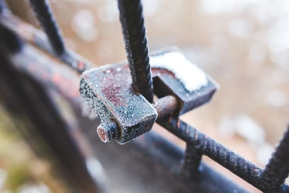
The cuplock joint is a forged steel ledger blade seated in a fixed lower cup welded to the standard, then captured by a sliding upper cup that drops over the blade and is hammered home to lock the connection [S1][S3].
That single mechanism replaces the loose wedge, bolt, or wedge-head of tube-and-coupler and ringlock systems, and is the reason a cuplock scaffold can be erected by a single crew without spanners, clips, or separate locking pins at the node [S1][S2].
Anatomy of the Node: Blade, Lower Cup, Upper Cup, Standard
The vertical standard is hot-dip galvanized steel tube, 48.3 mm OD, with a lower cup welded to the tube at 500 mm centre-to-centre intervals along its full length [S1]. Each lower cup is dimensioned so that the cup mouth accepts up to four ledger blade ends simultaneously, which is what allows four horizontal members to lock at one node without additional hardware [S1][S3]. The upper cup is a separate sliding collar that rides on the standard; when the operator drops a ledger blade into the lower cup and slides the upper cup down over the protruding blade ends, a hammer strike on the upper cup drives it onto the blades and locks the joint [S1][S3][S6].
The ledger itself is a galvanized steel horizontal tube with a forged blade (sometimes called an "end-fixing") press-formed or drop-forged at each end, so the blade and the tube are a single rigid component rather than a welded-on shoe [S1][S2]. Standard ledger lengths run from 0.9 m to 3.0 m in 0.3 m to 0.5 m increments depending on manufacturer, and the same part is used for guardrail height when installed at the appropriate node [S1][S3]. A representative stocking item, the 3-board ledger at 2 ft 7 in (0.79 m) and 7.19 lb, shows the typical size and weight band for a short-bay horizontal in a cuplock system [S5].
How the Locking Action Differs From Wedge and Ringlock Systems
The cuplock locking sequence is purely a vertical drop-and-strike: blade into lower cup, upper cup down, hammer blow to seat, done, with no rotating wedge, no through-bolt, and no separate locking pin at the node itself [S1][S3]. By contrast, ringlock systems use a rosette welded to the standard and a wedge head on the ledger that is driven into the rosette opening; cuplock uses two cups and a blade instead [S1][S8]. The functional consequence is that cuplock locks by axial compression of the blade between the two cups, while ringlock locks by wedge friction in a cast rosette, two different load paths with different inspection signatures [S1].
A second practical difference is directionality: cuplock's four-way lower cup is symmetrical around the standard, so any of the four orthogonal blade positions (and intermediate diagonals up to the cup geometry) are equally first-class connections, whereas the rosette arrangement biases toward eight cardinal directions [S1][S8]. This is why cuplock remains common on repetitive rectangular facades, slab-formwork support, and shoring grids, where the four-way node simplifies bracing layout [S1][S3][S7].
Spacing, Geometry, and Where the Joint Is Specified
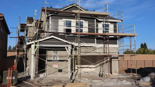
Node spacing is fixed at 0.5 m vertical intervals by the welded lower cups, so the standard is pre-engineered as a 0.5 m modular grid regardless of who supplies it [S1][S3][S7]. This 0.5 m grid, combined with horizontal bay lengths in 0.3 m to 0.5 m steps, gives a 0.5 m by bay-size modular footprint that is simpler to set out than the more flexible rosette spacing used on ringlock [S1]. Spigot connections between successive verticals are separate from the cup joint, using a spigot pin or bolt to transfer vertical load and resist uplift; the blade-end cup is not the vertical-load path, the tube wall is [S1].
In a typical access scaffold build the operator walks the standard with one hand, drops a ledger blade into the lower cup at the chosen level, then slides the upper cup down by thumb pressure before the final hammer tap, which seats the cup against the blade shoulder [S1][S3][S6]. The resulting joint is rigid against both vertical and horizontal swing, which is what makes the platform feel solid under foot and is the property a supervisor checks during handover inspection [S3][S6].
Load Path, Inspection, and Common Failure Modes at the Node
The vertical load path runs through the standard tube wall and the spigot, not through the cups or blades; the cups exist to restrain the ledgers and transfer horizontal shear and tension into the standard [S1]. This separation of duties is important for inspection: a properly seated blade sits flush with the top of the upper cup, and the upper cup, when struck, sits tight against the lower cup with no daylight visible [S1][S6]. If the upper cup is left proud, or the blade is only partially inserted, the joint carries by friction rather than by bearing and will loosen under cyclic loading [S3][S6].
Three recurring node-level problems show up in service: (1) the upper cup fails to seat fully because the hammer blow is too light, leaving a gap that lets the blade rock; (2) the blade is bent from drop-impact or over-loading, which prevents the upper cup from sliding down; and (3) the lower cup weld cracks, typically at the cup-to-tube fillet, which is a discard-the-standard condition rather than a repair [S1][S3][S6]. Hot-dip galvanizing protects the cup-and-blade interface from corrosion, but once the zinc is worn through at a high-cycle node the underlying steel wears fast, so used cuplock in coastal or wet service is commonly rejected on cup wear even when the tube is sound [S1][S3].
Components That Surround the Node: Standards, Braces, Transoms, Base Jacks
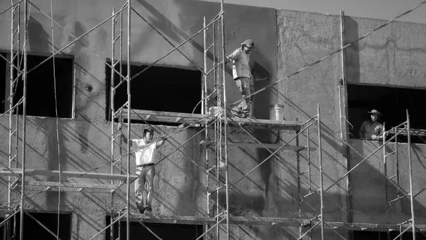
The standard is the structural spine that carries the welded lower cups, and is stocked in full lengths of 2.0 m, 2.5 m, and 3.0 m, plus intermediate 0.5 m and 1.0 m lengths for top-out levels, all with a spigot at the top end for stacking [S1]. The ledger is the primary horizontal and doubles as a guardrail; the transom, in many cuplock systems, is the same part installed at 90 degrees to support scaffold boards, and dedicated transom variants exist where the system requires a different blade orientation [S1][S3]. Diagonal braces, hop-up brackets, beam brackets, and cantilever frames all use the same cup-and-blade logic, which is what makes the system a true modular kit rather than a frame-and-brace scaffold [S3].
At the base, screw jacks with base plates handle uneven ground; the jack sits under the standard, and the standard's first lower cup is typically 0.5 m above the jack so the bottom node is clear of the ground [S1][S3]. Lock pins secure the spigot between stacked standards so the vertical load is continuous, while the cup joints handle only horizontal restraint, a deliberate split that simplifies both design and inspection [S1][S3].
Comparison Table: Cuplock vs Ringlock vs Tube-and-Coupler at the Node
Cuplock and ringlock both qualify as modular systems but use different node hardware, while tube-and-coupler is the older loose-fitting benchmark; the table below lines them up against the criteria a process engineer or scaffold supervisor actually uses to pick between them. [S3]
On locking hardware, cuplock uses a forged ledger blade captured between a fixed lower cup and a sliding upper cup struck with a hammer, ringlock uses a wedge head driven into a welded rosette with a hammer, and tube-and-coupler uses right-angle or swivel couplers tightened with a spanner on each end of every tube [S1][S8]. On connections per node, cuplock is rated at up to four, ringlock at up to eight (the rosette has eight holes), and tube-and-coupler is unlimited but is dependent on coupler count and torque [S1]. On tools required, cuplock needs only a hammer for the node, ringlock needs only a hammer for the wedge, and tube-and-coupler needs a spanner for every coupler [S1][S8]. On vertical modularity, cuplock is locked to 0.5 m by the welded cups, ringlock uses 0.5 m rosette spacing as well but with more node positions, and tube-and-coupler is free-form [S1]. On typical use, cuplock is preferred for repetitive shoring, slab, and façade bays, ringlock for complex industrial geometry, and tube-and-coupler for irregular access where a standard system does not fit [S1][S3][S7].
Standards Context and Sourcing Notes
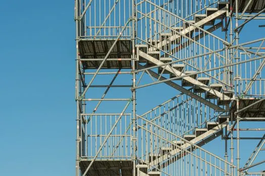
Cuplock system manuals from major manufacturers (Hünnebeck CUPLOK and equivalent regional brands) describe the same geometry: fixed lower cups welded to the verticals and a sliding upper cup that drops over the blade ends of the horizontals, locked with a hammer blow [S6]. The 500 mm welded cup interval, four-blade capacity per node, and forged blade end are consistent across the manufacturer documentation surveyed [S1][S2][S3][S6][S7]. For broader reading on the modular scaffold category and how cup nodes compare with other node types, see the scaffolding and locking assembly reference pages, and for the heavier equipment class that often shares a cuplock shoring grid, see construction machinery and equipment.
Two trackable signals for the next planning window are (a) any update to manufacturer CUPLOK user manuals covering revised cup-wear inspection criteria, since cup-wall thinning governs the re-use life of used cuplock stock, and (b) the spread of 0.5 m grid cuplock into mid-rise residential shoring where 1.0 m cuplock systems are currently the default, as the half-metre grid is more efficient for thin slabs and beam-and-block decks.
For related coverage, see Mechanical Dock Leveler Spring Tension: Adjustment Procedure and Field Limits.