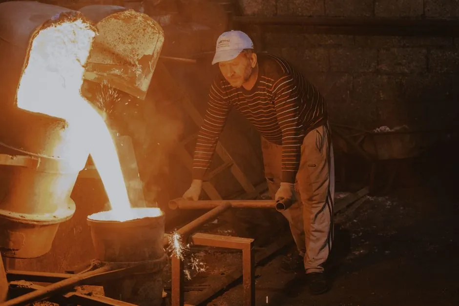
A cupola furnace cross section stacks six thermal zones vertically, with the tuyere belt supplying combustion air and the well zone between the tuyeres and the sand bottom collecting molten iron and slag [S2]. The tuyere openings are arranged in a staggered circumference pattern, typically 6–8 per row, blowing air from a surrounding wind box into the shaft at a defined height above the bottom [S3].
The well acts as a metal and slag reservoir that decouples combustion-zone aerodynamics from tap-out flow, which is why tuyere height above the sand bottom is a primary spec variable for any 0.5–10 t/h foundry or mineral-wool cupola build [S1]. The full cross section is conventionally drawn with the stack at top, then preheating, melting, reducing, combustion, and hearth/well at bottom [S5].
Vertical zone stack and the tuyere reference plane
The reference literature defines six zones of interest in a cupola: stack, preheating, melting, reducing, combustion, and hearth/well [S1]. The tuyere belt is the demarcation between combustion and the overlying reducing zone, and sits directly above the well: tuyeres admit air, gases rise and transfer heat, while liquid metal and slag fall into the well for storage before tap [S2].
In a 0.5 t/h foundry cupola the charge bed is sized so the idle-charge upper level sits a measured distance above the tuyere plane, which sets the actual combustion-zone thickness per charge composition [S4]. For cross-section drawings the tuyere plane is therefore drawn as a horizontal datum line: anything above it is gas-side heat transfer, anything below it is liquid residence.
Tuyere geometry, count and arrangement
A representative patent drawing of a cupola shows a refractory-lined steel shell, an external wind box fed by a blast pipe, and tuyere openings emerging through the inner wall in two staggered rows of four for a total of eight openings [S3]. The principle cited is that efficient melting requires CO2 and CO in substantially equal proportions at the melting zone with free oxygen substantially absent, and the smallest amount of O2 at the least height above the tuyeres [S3].
Practically this drives a design rule: total tuyere area is sized to a target specific blast volume per unit shaft cross section, and individual tuyere nozzles are spaced to give overlapping jets on the charge surface without leaving dead pockets. Cross sections in operating manuals show the tuyere belt as a clear rectangular band, with the wind box drawn as an annular chamber wrapping the lower shell.
Well zone depth and what it controls
The well is the portion of the cupola between the tuyeres and the sand bottom, and it serves to collect the metal and slag melted in the upper part of the furnace [S2]. Its depth is the difference between tuyere elevation and the sand bottom, and is set by tap-hole height plus a slag pool reserve.
A deeper well increases metal residence time and slag-metal separation, but it also lengthens the liquid column above the tap, raising ferrostatic head and the risk of bottom burn-through if refractory wears. Cross sections therefore always annotate the sand bottom line, the tap hole, the slag notch, and the well freeboard between tuyere and the quiescent bath surface.
Combustion chemistry reflected in the cross section
The combustion zone sits immediately above the tuyere belt, where incoming air meets descending coke; the reducing zone above it is where CO2 rising from combustion reacts endothermically with incandescent coke to give CO, which then preheats the descending charge [S2]. The classic requirement is a CO2:CO ratio near unity in the melting zone for efficient heat release plus carbon pickup into the iron [S3].
A taller reducing zone improves coke economy and carbon pickup, but pushes the melting front higher and shortens the effective preheating zone. Mineral-wool and continuous-melt cupolas therefore often use a tighter combustion/reducing stack than iron-foundry cupolas, a difference that is immediately visible when two cross sections are overlaid. For context on the combustion side, see Cupola Coke Bed Height: Spec for a Stable Combustion Zone, and for the charge above it, Cupola Charge Calculation: Coke, Iron, and Limestone Ratios.
Cross-section drawing conventions and common labels
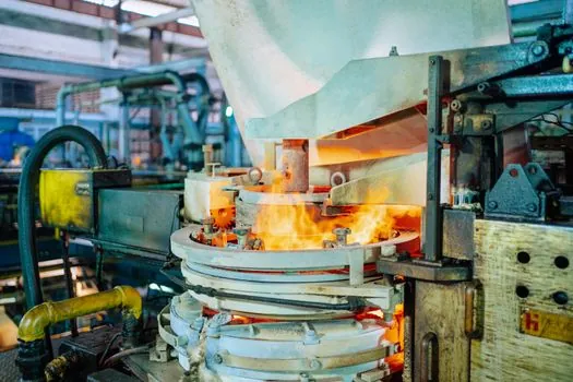
Standard cupola cross sections label: outer steel shell, refractory lining thickness, charging door at top, spark arrestor/cap, downcomer for off-gas, preheat and melting zones within the shaft, tuyere belt with wind box, well, sand bottom, and tap hole / slag notch at the base [S5]. The cupola furnace reference page collects the same drawing set used in textbooks and plant P&IDs.
When comparing cupolas, the most diagnostic single dimension in a cross section is the ratio of total stack height to inner diameter: cold-blast foundry cupolas typically run 3–4 stack-to-ID ratios, while hot-blast and mineral-wool cupolas run shorter and fatter. For buyers cross-shopping the related steel section category, this is the same shaft-diameter vs. height logic, just expressed in production rate per m2 of cross section.
Selection and operating constraints visible in the geometry
Tuyere height above sand bottom is the single largest lever on tap temperature and carbon pickup: raising the tuyere belt deepens the well, increases bath residence, and drops tap temperature for a given blast rate, while lowering it forces higher tuyere velocities and raises refractory wear at the belt. Sizing the well below the crucible furnace reference depth is a common drafting error, since a cupola well is open to blast pressure and a crucible well is not. [S2]
Operator-readable signals in the cross section: tuyere peep sights for flame color, tuyere-back pressure taps for specific blast volume, and thermocouples in the well for bath temperature. The upper level of the idle charge relative to the tuyere plane is a calculated, not measured, parameter, and a 2025 procedure proposes a method for determining its position from heat-load profiles [S4].
Trackable signals: 0.5–10 t/h cupola rebuilds where the new tuyere elevation is 200–400 mm above the old one, and where the well is deepened in parallel; published hot-blat conversions where a recuperator is added and the tuyere count changes from single-row 6 to staggered 8; cross sections published with measured idle-charge upper level, not just the nominal bed-height setpoint.
