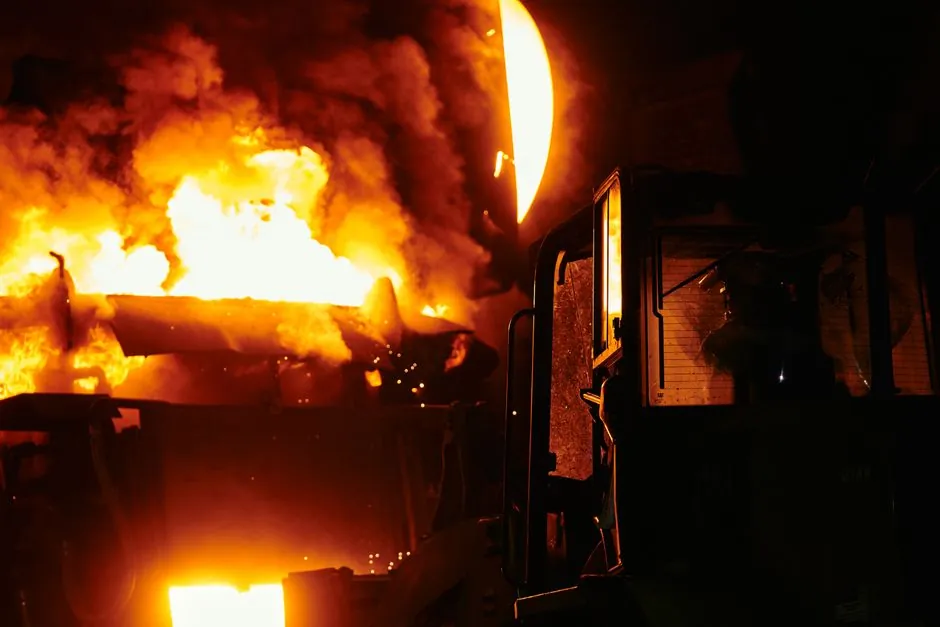
A cupola furnace is a vertical, cylindrical, refractory-lined shaft furnace charged from the top with alternating layers of metallic iron, metallurgical coke, and a flux such as limestone, with combustion air (blast) injected through tuyeres near the base to melt the descending charge and collect liquid iron in a well at the bottom [S1][S5].
For foundries that pour grey iron, ductile iron, or malleable iron castings in the 1,000-50,000 t/yr bracket, including pump housings, valve bodies, and fittings, the cupola is still the dominant bulk-melting workhorse in 2026, with reported rock-wool and iron-melting lines built around 3,000-30,000 t/yr single-cupola modules [S2].
What the cupola actually delivers in 2026 specifications
A typical 2026 cold-blast acid cupola is sized by inner diameter: small job-shop units run 500-700 mm ID at 1-3 t/h melt rate, mid-sized automotive and valve foundries use 800-1,200 mm ID at 4-12 t/h, and large foundries in the ductile-iron pipe and fitting class run 1,400-2,000 mm ID hot-blast cupolas at 15-30 t/h [S2].
Hot-blast cupolas with recuperative stoves hold tapping temperatures of 1,480-1,540 degC at the spout, which is the working window for ductile-iron pump and valve castings requiring 1,480 degC+ to feed heavy section thickness, while cold-blast units more typically tap at 1,420-1,480 degC for grey-iron body castings [S2].
Coke consumption in a well-managed 2026 cupola is 8-12% of metallic charge by mass for cold-blast and 7-9% for hot-blast, with iron-to-coke ratio and tuyere velocity (typically 30-50 m/s) the two levers that determine melt rate and carbon pickup [S2].
Why a pump-and-valve foundry would still pick a cupola
Cupolas also accept a wide, dirty charge mix, including returns, sprues, borings, and purchased scrap, which is why they remain common in valve and foundry operations that consume mixed ferrous scrap, while induction furnaces prefer clean, sized charge to avoid bridge-ups and slag inclusions [S2].
For foundries that pour carbon-steel valve trim or stainless pump components in addition to iron bodies, the cupola is paired with a holding furnace or a separate crucible furnace line, since the cupola itself is fundamentally a ferrous iron melter and is not used to melt stainless or non-ferrous alloys [S2].
Limitations and failure modes that decide it out
The cupola is a continuous-feed melter: it cannot be idled below about 40% of rated throughput without the tuyere zone cooling and coke burning erratically, so it loses to melting furnace options in foundries that run 1-2 short shifts a day on mixed alloys [S2].
Emissions are the second disqualifier: cupolas produce a high-volume, CO-rich, particulate-laden off-gas that requires a wet scrubber, baghouse, or afterburner, and 2026 installations for valve and pump foundries in non-attainment areas typically add a waste-gas burning furnace and heat exchanger to the gas train to stay inside the local limit [S2].
Cupola slag is a recognised by-product with a documented reuse track record in cement and concrete aggregate replacement, which is a useful data point for foundries trying to close a slag-disposal loop [S3].
Selection criteria mapped to pump and valve castings
For a foundry pouring ASTM A48 Class 30/40 grey-iron valve bodies in the 5-50 kg range, a 700-900 mm ID cold-blast cupola at 2-5 t/h with a 1,440-1,480 degC tap target is the conventional fit, and the same unit can feed ductile-iron valve Bonnets and pump volutes if the cupola furnace is run with low-sulphur coke and the iron is desulphurised in the ladle [S2].
For high-pressure valve and pump body castings that require radiographic-quality ductile iron to ASTM A536 60-40-18 or 65-45-12, a hot-blast cupola at 1,500 degC+ tap, paired with a magnesium treatment ladle and a channel holding furnace, is the standard 2026 cell in many tier-one valve foundries [S2].
Foundries that need to swing between iron and steel or non-ferrous melts for the same pump-and-valve customer should not rely on a cupola as their single melting asset; a duplex arrangement with a coreless or channel induction unit as a backup is the more flexible, if more capital-intensive, layout [S2].
Standards, charge materials, and operating discipline
Cupola iron foundries serving pressure-containing castings typically reference ASTM A48 for grey iron, ASTM A536 for ductile iron, and the ASME B16.34 valve standard for body and Bonnet material acceptance, with each heat traceable through a charge-card and tap-record system [S2].
Refractory life on a 2026 acid cupola is typically 6-18 months depending on campaign length, and water-cooled copper tuyeres are now standard above 800 mm ID because they cut tuyere-belt refractory erosion, which is the classic forced-outage mode for a cupola mid-campaign [S2].
Who should and who should not specify a cupola
The cupola is the right pick for a foundry that runs 3 shifts, pours 5-30 t/h of iron, and tolerates a continuous, single-alloy melting profile; it is the wrong pick for a job shop that runs 1 shift, pours 2-3 alloys in a day, or sits inside a tight urban emissions cap [S2].
A pure pump-and-valve foundry pouring 80% ductile iron bodies, with the balance in stainless or carbon-steel trim cast elsewhere, can be built very efficiently around a single hot-blast cupola plus desulphurisation and Mg-treatment, but adding any meaningful stainless or bronze trim in-house pushes the design toward an induction duplex [S2].
Foundries evaluating a greenfield cupola in 2026 should expect a 6-12 month permit and construction lead time because of the off-gas treatment scope, and they should plan the slag-handling yard, coke-storage silo, and charge elevator as integral parts of the cupola cell, not as afterthoughts [S2][S3].
Track next signals: revised 2026 cupola emissions guidance from the EU IED BREF review and any 2026-2027 update to ASTM A48/A536 acceptance criteria for thin-wall valve bodies; both will shift the capex math on cupola vs induction retrofits for pump and valve foundries.