For 2026 industrial and battery-powered designs, the fastest path to a correct DC-DC converter choice is to fix the topology from the input/output relationship, then verify the four data points that drive reliability: input voltage range, output current, isolation class, and inductor ripple ratio of 20-40% of load current [S4][S5].
Across February-August 2026 OEM guidance, buck, boost, buck-boost, SEPIC, flyback, and forward converters remain the six topologies spec sheets reach for first, with module-versus-discrete decisions dominated by EMC risk, isolation voltage, and time-to-market rather than unit price [S1][S2][S3]. A typical design targets 30-40% ripple; below 30% the inductor grows 2-3x and transient response slows from roughly 15 microseconds to 50 microseconds, while above 40% the output capacitor ripple-current rating is exceeded and EMI filtering becomes mandatory [S5].
Topology by input/output relationship
A buck converter steps down only and is the default where a 24V rail feeds 12V or 5V logic; a boost converter is the inverse and is used for 5V to 12V LED or small-motor drive; a buck-boost or SEPIC handles batteries whose voltage crosses the output rail during discharge, with SEPIC preserving input/output polarity [S2].
For galvanic isolation between functional domains, flyback stores energy in the transformer during the on-time and releases it during the off-time, making it the workhorse for adapters, chargers, and auxiliary rails up to roughly 100 W; forward converters transfer energy directly through the transformer during the on-time and scale into telecom and server power where higher isolated power is required [S2][S3]. Choose SEPIC for non-inverted step-up/step-down in automotive and portable gear, and choose buck-boost only when polarity inversion is acceptable and the converter can be smaller [S2].
Inductor selection: the three numbers that actually matter
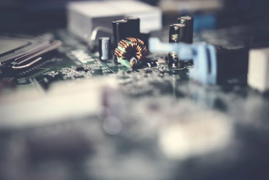
Three inductor parameters decide whether a DC-DC prototype survives the bench: inductance L, saturation current I_sat, and DC resistance DCR; ripple current is governed by delta-I equals V times D times T divided by L, with a typical target of 30-40% of load current [S4][S5].
I_sat is the DC bias at which L drops by 20-35% depending on the manufacturer test method, and exceeding it collapses inductance within 5-10 switching cycles and typically destroys the switching FET; I_rms is the current that produces a 40 degree Celsius hotspot above ambient, and represents the continuous thermal limit [S4]. In a documented 12V-to-3.3V / 5A buck case, swapping a 10 microhenry molded inductor at 28 milliohm DCR for a composite-core part at 18 milliohm DCR cut I-squared-R loss from 0.7 W to 0.45 W, dropped junction temperature from 78 degrees Celsius to 52 degrees Celsius, and eliminated audible whine that had been driven by saturation at the ripple peak [S5]. DCR tolerance of plus or minus 15-20% also causes current imbalance in paralleled inductors, and 18% imbalance has been measured on a three-phase buck from DCR mismatch alone, so Kelvin four-wire measurement at room temperature scaled by 1.39x for 100 degrees Celsius copper is a real production gate, not paperwork [S5].
Module versus discrete isolated design
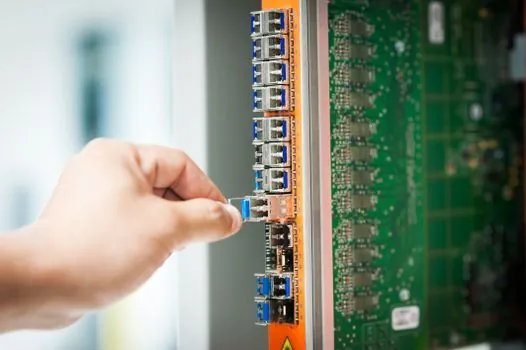
Isolated DC-DC modules ship as pre-qualified, certified blocks with defined EMC performance, verified functional or reinforced isolation, and minimal integration effort, while IC-based discrete designs expose the transformer, rectifier, and magnetics so the engineer can optimize bill-of-materials and thermal coupling at high production volume [S3][S7].
For unregulated transformer driver ICs the output is set by input voltage, turns ratio, load, and efficiency; when output accuracy matters, a downstream LDO or regulation stage is added on top of the isolated block [S3]. Module wins when development risk, design complexity, and time-to-market dominate; discrete wins when production volume is high enough that bill-of-materials optimization and application-specific thermal integration pay back the extra transformer-design expertise and layout work [S3]. Late-failure modes in isolated supplies typically trace to electrolytic capacitor aging, optocoupler CTR drift, or thermomechanical stress on the transformer, which is why reinforced-isolation modules with published MTBF and full bill-of-materials disclosure are favored in functional-safety paths, while discrete remains common where size, cost-per-watt, or unusual input ranges rule out catalog parts [S7]. See the DC-DC converter reference page for topology-level definitions and the DC power supply reference for how modules compare with linear and switching supplies at the system level.
Industrial IoT and battery-powered constraints
Industrial IoT endpoints need wide input ranges (often 4.5-36 V or 6-60 V) to ride transients on 12V and 24V rails, low quiescent current in the microamp range to stretch battery life, and high switching frequency above 1 MHz to keep the inductor under 2 mm in height for sealed enclosures [S1].
Engineers evaluating buck converter ICs for IIoT should rank input voltage range, output current capability, switching frequency, and efficiency together; an IC with 92% peak efficiency at 1 MHz but only 5 V maximum input fails a 24V-rail design, and a 60 V part running at 200 kHz is too tall to fit the box [S1]. For battery-powered products where the cell voltage crosses the desired rail, a buck-boost or SEPIC is mandatory, and a buck-only IC forces a discrete boost front-end that costs efficiency, board area, and a second EMC signature [S2]. When the system must hold 5V or 3.3V through end-of-discharge on a single-cell Li-ion (roughly 4.2 V down to 3.0 V), buck-boost is the topology, and SEPIC is the variant when input and output grounds must stay common [S2].
Selection criteria mapped to duty
Match the variant to the duty before picking a part: 24V-to-5V logic rail with no isolation chooses buck; USB-C or 12V battery to 24V motor chooses boost; 12V lead-acid to 12V load across discharge chooses buck-boost or SEPIC; sensor or gate-drive isolation at under 10 W chooses flyback; telecom or server 48V-to-low-voltage isolated POL chooses forward or full-bridge module; field-bus node with reinforced isolation to a hazardous area chooses a pre-certified isolated module over a discrete flyback [S2][S3][S7].
A criteria-based comparison of the four most common choices on a 12V nominal input: buck (Vin 12V, Vout 3.3-5V, efficiency 90-96%, isolation none, typical duty point-to-point logic), SEPIC (Vin 4-20V, Vout 12V fixed, efficiency 80-88%, isolation none, typical duty battery to fixed rail), flyback (Vin 12-48V, Vout 5-24V isolated, efficiency 80-90%, isolation functional or reinforced 1.5-5 kV, typical duty isolated I/O and gate drive), forward (Vin 36-75V, Vout 5-12V isolated, efficiency 85-92%, isolation reinforced 2.25-3 kV, typical duty telecom 48V POL) [S2][S3].
Who should not pick the mainstream option
Do not pick a non-isolated buck for any rail that crosses a safety barrier, an SELV/PELV boundary, or a ground-potential difference above a few volts, because the lack of galvanic isolation will turn a downstream fault into an input-rail fault [S2][S7]. Do not pick a discrete flyback when the production run is under roughly 10,000 units per year and the schedule is tight, because transformer magnetics design, layout, and EMC pre-compliance will dominate the cost curve and a pre-certified module will land faster and cheaper [S3].
Do not pick a buck-boost when SEPIC will do the job, because buck-boost inverts output polarity and that polarity flip rules out loads that need a common ground; SEPIC delivers the same wide input range with a non-inverted output, at the price of an extra coupling capacitor and slightly lower peak efficiency [S2]. Do not pick a ferrite-core inductor for a high-ripple, high-bias current rail without checking core loss at the actual DC bias, because ferrite curves are usually published at zero bias and the real loss at 5 A bias can run roughly 3x the datasheet typical, as the Shareway case showed when a 340 mW real loss replaced a 120 mW datasheet number [S5].
Shortlist logic and verification before release
Build a three-row shortlist: row 1 is the topology that matches the input/output relationship, row 2 is the isolation class (none, functional 1.5 kV, reinforced 2.5-3 kV) and the module-versus-discrete call, row 3 is the inductor sized to 30-40% ripple with I_sat 30% above peak and DCR verified at the actual DC bias [S2][S3][S4][S5].
Before release, measure the inductor's L and core loss on a precision magnetics analyzer at the circuit's actual DC bias, not at the datasheet zero-bias point, and verify DCR with a four-wire Kelvin milliohm meter, then scale by 1.39x for a 100 degree Celsius hotspot [S5]. For isolated rails, cross-check that the module's published isolation voltage, MTBF, and reinforced-insulation grade match the safety case, and that the EMC signature has been characterized on a real bench rather than assumed from the datasheet [S3][S7]. Two trackable signals to watch into late 2026: tighter industrial-rail EMI immunity standards pulling switching frequency higher and inductor height below 2 mm, and wider adoption of integrated transformer-driver plus synchronous-rectifier IC pairs that close the gap between module simplicity and discrete cost in the 5-30 W isolated range [S1][S3]. Readers comparing converter choices against full system power architectures can also see how the same isolation rules apply in the industrial UPS versus switching power supply sizing guide.
Component reference pages worth checking: fiber converter.