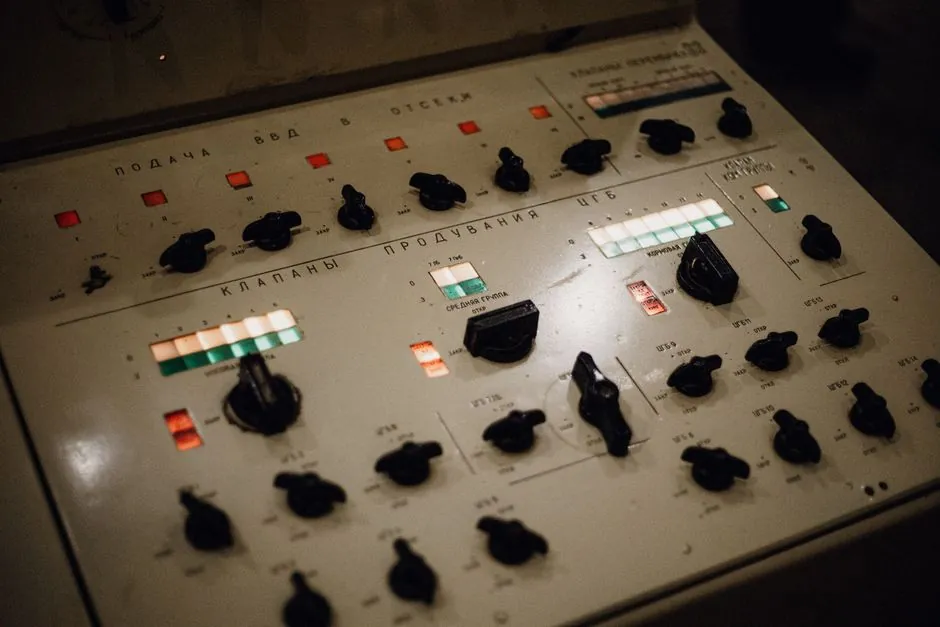
An MCC is a centralized assembly of motor starters, protection devices, control devices, and buswork used to distribute power and operate multiple motors, with low-voltage designs commonly serving systems up to 600 V [S3][S5].
Classification depends on several separate dimensions: system voltage, NEMA wiring class and type, enclosure, protection method, control method, and application, so an MCC cannot be specified from the label “motor control center” alone [S2][S4].
Low-voltage MCCs normally handle circuits up to 600 V and cover a broad range of industrial motors, including fractional-horsepower equipment where local panels or combination starters may be more practical [S5].
An MCC may contain feeder devices as bucket items [S4]. A feeder unit broadens the assembly beyond motor starting, but it does not change the core protection duties of the connected motor circuits.
Application classification is more useful during concept design than the voltage label alone.
NEMA wiring classes and Types A, B, and C
Under the NEMA classification system, MCC wiring is organized into Class 1 or Class 2 and Types A, B, or C; Class 1 wiring places contactors, overload relays, and protective devices in the same individual unit as the starter [S7].
For cable routing between panels, trays, and terminations, the physical separation should also be reviewed against the project cable-tray design.
Starter-based and solid-state MCC types
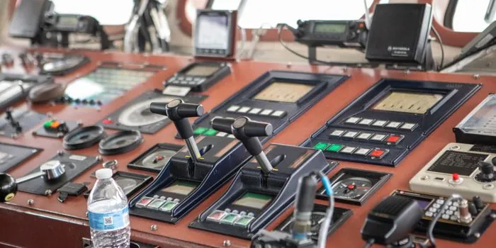
The basic motor starter combines a contactor with an overload relay, while a combination starter adds a branch-circuit protective device and disconnecting means within a common enclosure [S3].
Conventional electromechanical starters support simple on-off control through contactors and pilot devices. Soft starters and variable frequency drives may be installed in MCC buckets [S4].
The choice is criteria-based rather than stylistic.
Protection, short-circuit ratings, and control levels
An overload relay protects the motor from sustained overload but does not protect the feeder wiring from a short circuit, so a circuit breaker or fuses are also required [S3].
MCC bus systems must also be assessed for fault strength, and arc-flash risk requires attention because energized maintenance can expose personnel to hazardous energy [S4].
Protection scope can be expanded with feeder devices, soft starters, VFDs, and monitoring or metering functions. The bucket remains the modular unit containing the equipment needed to start, stop, and protect its assigned load [S4].
Enclosure and physical construction classifications
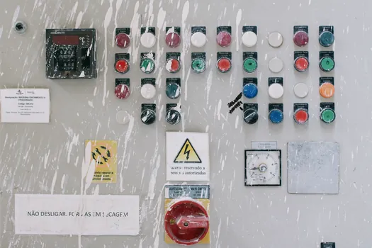
Common MCC construction uses vertical sections, horizontal and vertical bus systems, wireways, and removable modular units called buckets [S4]. This physical arrangement differs from the NEMA wiring classification and should be recorded separately in project documentation.
NEMA enclosure types and indoor or outdoor suitability form another selection layer [S4]. MCCs often present arc-flash risks when equipment must remain energized during maintenance, and arc-resistant remote racking technology can help improve operator safety [S4].
Common MCC construction designs include vertical sections, horizontal and vertical bus systems, wireways, and modular control units called buckets [S4]. Bucket dimensions, withdrawability, cable-entry space, and planned spare units must be coordinated before the enclosure arrangement is frozen [S2][S6].
Where control conductors enter through glands, the gland selection must match the cable construction, entry method, and enclosure requirement. This interface is addressed in the cable-gland selection reference.
Basic, advanced, and network-connected MCCs
MCCs provide a centralized location where motors can be controlled, monitored, and diagnosed, and basic AC motor control commonly uses a contactor and overload relay operated by start and stop pushbuttons or other pilot devices [S3][S4].
A monitored MCC can expose motor operating data for diagnostics and predictive maintenance, reducing the need to inspect every controlled motor physically [S5]. Network-connected control adds supervision capability, but communication requirements must be defined during concept design rather than added after the power sections are ordered.
Advanced control is suitable for facilities with many motors, coordinated processes, or formal maintenance programs. A basic MCC is usually sufficient when duties are repetitive, access is local, and the mechanical equipment does not require process synchronization or speed adjustment [S9].
Selection criteria and common failure modes
An MCC specification should define voltage, motor load, starting method, number of starts, fault-current level, bus rating, wiring type, enclosure type, arc-flash strategy, and required communications. Omitting the wiring class and type can create incompatible maintenance and expansion arrangements even when the physical cabinet dimensions appear correct [S2][S7].
Common failures include worn bucket interlocks, damaged connectors, contact wear, coil failure, nuisance breaker tripping, incorrect overload settings, thermal degradation, and loose busbar connections [S3][S5]. These are inspection points, not a substitute for an engineered short-circuit and protection study.
MCCs are not the right answer for every motor. A single small motor, a geographically isolated load, or a stand-alone pump can be served more economically by a local panel or combination starter, particularly when centralized monitoring and spare-unit standardization offer little benefit [S3].
For the next design step, request the one-line diagram, motor schedule, fault-current study, and NEMA wiring classification, then verify each bucket against its assigned motor starting duty before releasing the assembly for fabrication [S2][S6].