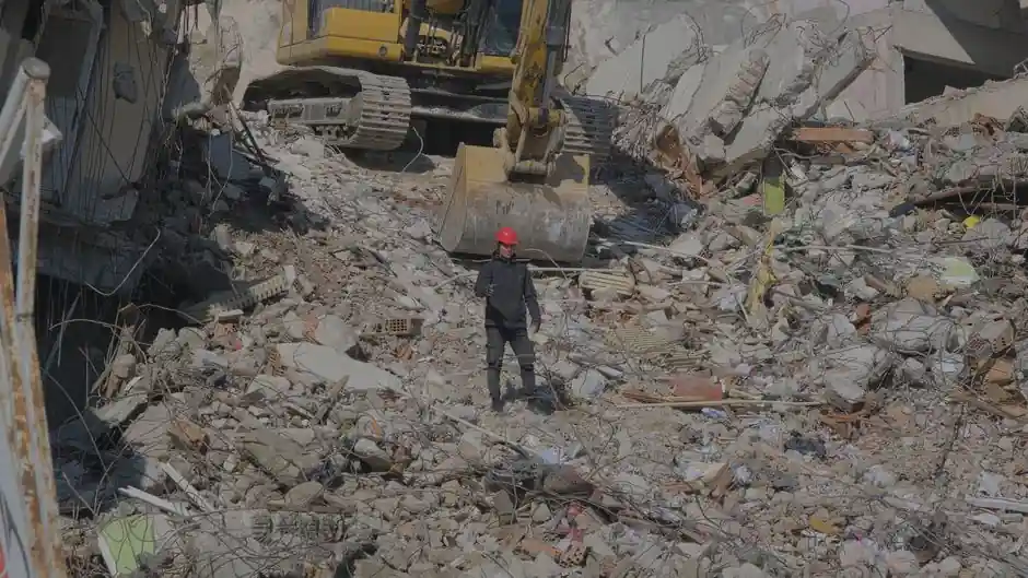
Across pneumatic and electric demolition hammer fleets on concrete and road-recycling sites, four failure families account for the majority of unplanned downtime: impact-performance degradation, mechanical wear and seizure, cuttings-removal system faults, and power-transmission/seal failures [S4].
Handheld electric breakers typically deliver 5-65 J impact energy at 1300-3000 bpm, while heavy 30-70 kg hex-class hammers run 60-110 J at 800-1500 bpm for road, foundation, and trench work [S1]. Most field failures sit inside those four buckets, not in the motor or the breaker mechanism itself [S4].
Impact-Performance Loss: Power Medium and Air-Distribution Faults
Pneumatic hammers lose impact force when compressor pressure drops below the 0.6-1.2 MPa window typical for hard-rock drilling, when supply lines leak, or when moisture and dust contaminate the air, accelerating seal wear inside the valve block [S4].
Inside valveless designs, the piston/cylinder flow grooves wear and clog with cuttings, delaying flow reversal and lowering impact frequency, which is the most common root cause when an operator reports "the hammer just feels weak" [S4]. Worn piston faces and worn bit tails increase the contact clearance so a measurable share of each stroke's energy never reaches the bit [S4].
Mechanical Wear, Seizure, and Piston Breakage
Inadequate lubrication, ingress of rock cuttings, and long continuous-duty cycles raise piston/cylinder wall friction until the piston seizes, cracks, or fractures outright; the same conditions gall the piston undercut and propagate fatigue cracks [S3].
For DTH-class hammers used in hard-rock demolition, drill-string damage from thread loosening and hole deviation adds bending moments that buckle the string, accelerating both hammer wear and bit consumption [S4]. Front and rear subs, the threaded connectors between hammer and bit and between hammer and drill string, strip or deform under sustained torque and vibration if not re-torqued to spec [S4].
Bit-Side Failures: Chipping, Drift, and Jams
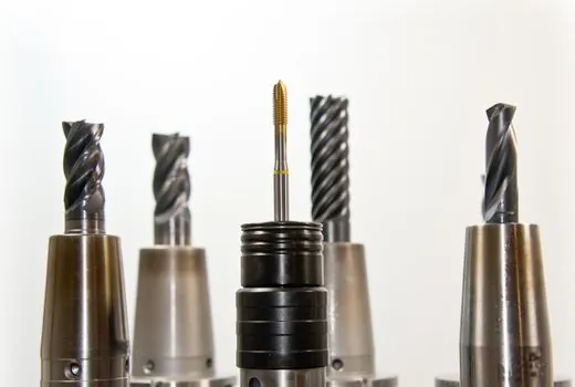
Bit tip chipping is the most common field failure on demolition and rotary hammer bits, with documented cases where a YG8C tungsten carbide tip chipped in 5 minutes on C50 concrete and was resolved only by stepping up to YG11C grade [S2].
Drift, the bit wandering off the marked hole centre, comes from uneven start surfaces, rebar deflection, density variation in the substrate, and tool weight imbalance; general construction tolerates deviation up to 5 mm per 100 mm of depth, precision installation demands 2 mm/100 mm, and chemical-anchor holes need 1 mm/100 mm [S2].
Jams, the most frustrating field event, are driven by dust accumulation in deep holes, rebar entrapment, hole-wall collapse in loose concrete, and thermal expansion of an over-heated bit; the safe release sequence is immediate power cut, then a low-speed reverse attempt only if the tool supports it [S2].
Power-Transmission and Seal Failures
Drive sub fractures trace to gaps between the drive sub shoulder and the outer tube, loose threaded joints, insufficient feed pressure, and grease-starved threads, all of which the operator can flag with a pre-shift torque check [S3].
Cracked drive subs almost always come from sledge-hammer abuse during assembly; the right tool is a tong or chain, never a slugging bar, and the same rule applies to spline surfaces that transfer torque from hammer to bit [S3]. On the electric side, common field reports name worn locking bolts and O-rings hardened or burnt by an oil leak, which lets the mechanism run dry internally and accelerates wear on the hammer mechanism itself [S5].
Prevention: Lubrication, Cooling, and Operator Discipline

For rotary hammer and demolition bits, the published prevention protocol is concrete-grade matched carbide (C40+ demands YG11C or harder), start RPM held to 300-500, a 30-second cooling break every 10-15 holes, and a rebar-detector sweep before laying out the hole pattern [S2].
For pneumatic and DTH tools, the same published protocol applies: torque threads to spec with the right grease, raise feed pressure in unconsolidated ground, and use a foam flush at the end of every drilling cycle to clear cuttings from the hammer body before they migrate into the piston undercut [S3]. Operator PPE, hearing protection, safety glasses, gloves, safety shoes, and a dust mask, is non-negotiable because demolition hammers routinely exceed 100 dB(A) at the operator station [S6].
Comparison: Failure Mode vs Root Cause vs Field Fix
Four decision criteria separate a "weak hammer" complaint from a "stuck hammer" complaint, and they map cleanly to four different fixes, so the dispatch decision should run on symptom first, not on tool brand. [S3]
Impact loss points to power-medium pressure, valve wear, or piston-face clearance; mechanical seizure points to lubrication interval and cuttings ingress; bit chipping/drift points to substrate grade, rebar, and start technique; handle/seal vibration points to O-rings, locking bolts, and internal oil leaks [S2][S3][S4][S5]. A pre-shift demolition hammer inspection checklist should pull a sample from each bucket rather than only spot-checking the breaker mechanism.
Sourcing, Standards, and Adjacent Reading
Operator-side failure data and bit-grade recommendations come from manufacturer application engineering notes (S2, S3, S4, S5) and from a published demolition hammer testing and commissioning procedure; broader construction machinery and equipment selection context is in the GlobalSpec engineering reference (S1). [S2]
Trackable signals for the next 90 days: OEM field bulletins on piston-face clearance limits, bit-grade updates for C50+ concrete, and any revision to the 0.6-1.2 MPa hard-rock air-pressure window cited above [S4].