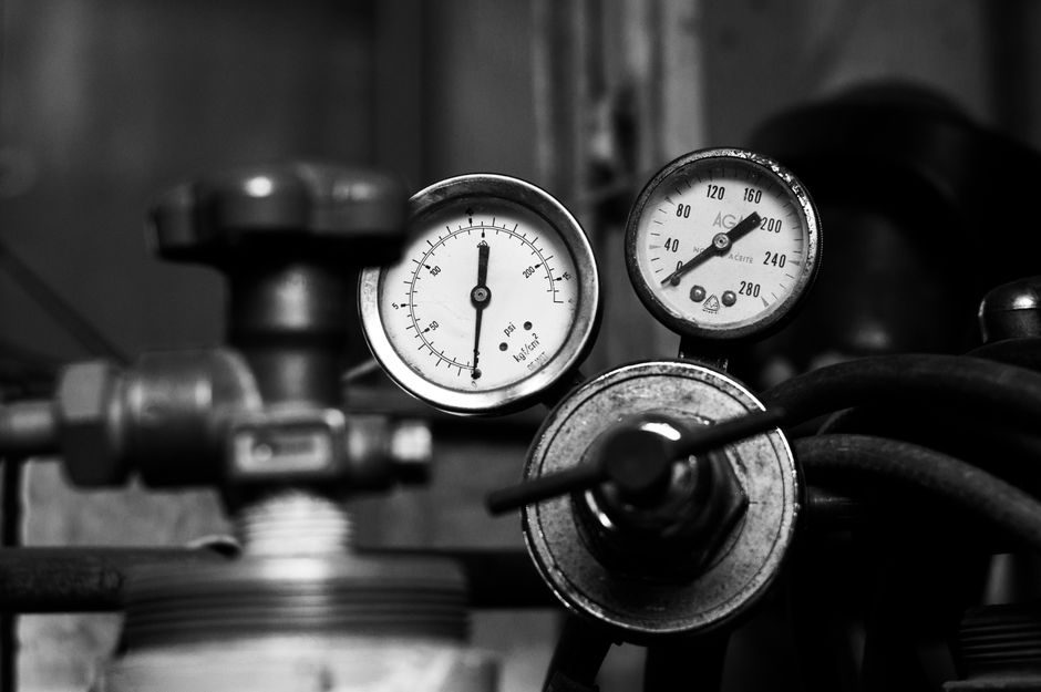
Specifying a diaphragm valve in 2026 starts with matching a real operating window to a named product family: BERMAD's WW-745 deep-well pump control valve covers DN 40–600 mm (1.575–23.622 in) at 25 bar (362.6 psi) and is sold as electrically, hydraulically, or hydraulically-operated with a monobloc seat and modulating actuator [S1].
The same vendor's 105-M landscape valve occupies a far smaller footprint — DN 40, 50, 65, 80 mm (1.575–3.15 in) — but ships in engineered plastic with an articulated flange and a Flexible Super Travel (FST) diaphragm tuned for low actuation pressure [S2]. Reading those two data sheets side by side shows why "diaphragm valve" is a category, not a SKU, and why diaphragm valve selection work is fundamentally a duty-matching exercise.
DN, PN, and the Size Band You Actually Need
Working DN size band is the first cut: the WW-745 ranges from DN 40 to DN 600 mm and is designed to "meet size and dimensions requirements of various standards," per BERMAD's published product copy [S1]. The 105-M, by contrast, sits at DN 40–80 mm and is line-pressure driven, which means the upstream pump curve — not the valve's PN rating — sets the available actuation force [S2].
Pressure class must be derated against temperature and media: the WW-745 publishes a 25 bar (362.6 psi) ceiling, and that figure only holds while the elastomer diaphragm and body liner stay within their qualified envelope. Forged vs. cast body, and lined vs. unlined internals, change the PN-to-temperature slope materially, so spec the body rating, liner rating, and diaphragm rating as three separate numbers rather than a single "PN class." Diaphragm pump duty and diaphragm valve duty share elastomer limits but diverge sharply on dynamic vs. static cycling, which is why the same elastomer grade cannot be lifted from one data sheet to the other.
Body, Liner, and Diaphragm Material Decision Tree
Material selection is the second cut and is dominated by chemistry, not by pressure. The 105-M uses engineered plastic with articulated flange connections that "eliminate mechanical and hydraulic stresses," giving chemical and cavitation resistance in a small irrigation-class package [S2]. The WW-745 markets "high quality materials" and a "protected diaphragm" without committing to a specific alloy in the catalog copy, so a chemical compatibility check against the named media list is mandatory before quoting [S1].
Three practical rules from the published data: (1) EPDM, FKM, and PTFE are the three common diaphragm elastomers, and each has a published temperature ceiling that must be checked against the maximum process temperature, not the design temperature; (2) abrasive duty — sand, pebbles, slurry — kills elastomer diaphragms fast, which is why the WW-745 is specifically marketed as "for sand" with a hydrodynamic body designed to keep debris out of the diaphragm chamber [S1]; (3) the FST diaphragm on the 105-M "prevents diaphragm erosion and distortion" but only at the line sizes and pressures it was engineered for, so do not extrapolate it to higher-DN service [S2].
Actuation: Manual, Hydraulic, Electric, and Pneumatic
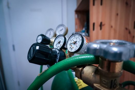
Actuation choice is the third cut and is driven by control philosophy, not by valve size. The WW-745 is offered in three actuation flavors — electrically-operated, hydraulic, and hydraulically-operated — and is described as a "modulating" valve suitable for "low flow rates" with "excellent and highly effective modulation capacity for high differential pressure applications" [S1]. That phrasing matters: modulating duty with high ΔP is a cavitation risk, and a double-chamber actuator with a V-Port throttling plug is the published mitigation [S1].
The 105-M is hydraulically operated only and is published as On/Off in response to a pressure command, with "low actuation pressure" listed as a design benefit [S2]. Translating that into a spec: if the loop needs proportional control at ΔP > 5 bar, the 105-M is the wrong tool and a modulating-class valve from the WW-745 family is the correct starting point. For solenoid-piloted loops, the Solenoid Valve 2026 selection map pairs naturally with diaphragm valves as a pilot stage, but only when the pilot flow can be sourced from line pressure — the 105-M is line-pressure driven, while solenoid pilots typically need an external pressure differential.
Cv / Kv Calculation: Where the Real Selection Error Happens
The most common sizing error is choosing DN first and Cv second. Correct order is the opposite: compute required Cv from flow, specific gravity, and ΔP using a standard valve-flow coefficient equation, then pick the smallest DN that delivers the required Cv with at least a 10–20% margin. The published WW-745 description claims "ultra-high flow capacity" and "low pressure loss" for the Y-pattern body used in the 105-M [S2], but BERMAD does not publish a Cv table per trim in either catalog excerpt, which means the buyer has to request a Cv vs. travel curve from the factory for any non-trivial modulating duty [S1][S2].
For on/off service, required Cv at design flow with ΔP at the valve usually lands well below the valve's maximum Cv, so DN 50 will commonly work for a duty that a less disciplined specifier might oversize to DN 80. For throttling service, the same valve must deliver the design Cv at 60–80% of rated travel, otherwise the trim operates in a near-closed regime that accelerates diaphragm fatigue and promotes cavitation. The comparison grid below captures the practical split between the two product families the research actually documents.
Application Matrix: Which Diaphragm Valve Goes Where
Mapping published products to real duties is a faster way to shortlist than re-reading every catalog. The table below uses only data that appears in the cited research.
Comparison on four selection criteria (BERMAD WW-745 vs. BERMAD 105-M):
1) Size band — WW-745: DN 40–600 mm; 105-M: DN 40–80 mm. Pick WW-745 when the line is above DN 80, and 105-M when it is at or below DN 80 [S1][S2].
2) Pressure rating — WW-745: 25 bar (362.6 psi) published ceiling; 105-M: not stated numerically, marketed as line-pressure driven with low actuation pressure. Pick WW-745 for any duty where the published PN must be defended on paper [S1][S2].
3) Control function — WW-745: modulating, double-chamber actuator, V-Port throttling plug optional; 105-M: hydraulic On/Off with FST diaphragm. Pick WW-745 for proportional control and high-ΔP throttling; pick 105-M for solenoid-piloted open/close at irrigation-class flows [S1][S2].
4) Media/environment — WW-745: explicitly "for sand" with hydrodynamic body and "drip tight sealing" for pump mains; 105-M: "highly durable, chemical and cavitation resistant" engineered plastic for landscape water. Pick WW-745 for raw water with debris, and 105-M for clean landscape water with chemical exposure [S1][S2].
For chemical-plant duty, the broader diaphragm valve selection map lines lined plastic and fully PTFE-lined bodied variants up against MSS SP-88 dimensional practice (MSS SP-88 is the published Manufacturers Standardization Society standard practice for diaphragm valves, listed at MSS SP-88-2015 in the research) [S4]. That dimensional standard is what lets a buyer swap a BERMAD, an ITT, or a Gemu valve on the same pipe flanges without re-engineering the line, and it is the single most useful cross-reference when the published Cv curve is not in the catalog.
Limitations, Failure Modes, and When Not to Specify a Diaphragm Valve
Diaphragm valves fail in predictable ways that buyers should price in. First, the elastomer diaphragm is a wear part with a published cycle life — typically far below a metal-seated ball or plug valve — so any duty that cycles more than once per minute on modulating service will eat diaphragms on a maintenance schedule measured in months, not years. Second, high-ΔP throttling at small openings generates cavitation, and even a "protected diaphragm" with a V-Port plug [S1] will not survive sustained cavitation without vacuum-breaker or anti-cavitation trim.
Third, the published descriptions explicitly call out two failure-prone duties: the WW-745 markets itself for "sand" and pump mains with debris [S1], which implies that clean, particulate-free service is the easier case and that dirty service requires the hydrodynamic body and active check logic to keep debris out of the diaphragm chamber. The 105-M, on the other hand, is sized for clean landscape water and does not publish a debris-handling claim [S2]. A buyer who routes a 105-M onto a raw water main with grit will see diaphragm failure well before the published cycle life. For solenoid-piloted control loops in clean service, the data-center cooling solenoid shortlist is a useful cross-reference, because the same "stay-out-of-cavitation" logic applies to the pilot stage of any hydraulically-operated diaphragm valve.
Standards, Sourcing, and What to Verify Before Signing the PO

Three documents should be on the desk before any diaphragm valve PO is cut. First, MSS SP-88-2015 "Diaphragm Valves" is the published dimensional standard practice that lets a buyer confirm face-to-face, flange drilling, and body dimensions line up with the line drawing [S4]. Second, the manufacturer's published Cv vs. travel curve, which both BERMAD catalog excerpts in the research point to but do not include [S1][S2]. Third, a written chemical compatibility statement against the named media, the maximum process temperature, and the cleaning chemistry — because the elastomer grade, not the body, is what sets the upper temperature limit in lined diaphragm valves.
Two trackable signals to watch over the next procurement cycle: (a) factory Cv curves for the 700 SIGMA EN/ES and 105-M product families, which BERMAD publishes on request but does not appear in the public catalog data sheets reviewed here [S1][S2]; (b) the diaphragm cycle-life warranty terms, which are quoted separately from the body warranty and are the number that actually drives total cost of ownership on modulating service. For buyers comparing diaphragm valves to other linear or rotary control valves, the linear guide and crossed roller guide encyclopedia entries cover the mechanical-motion side of valve actuators and are useful background when the actuation stage is being specced separately from the valve body.