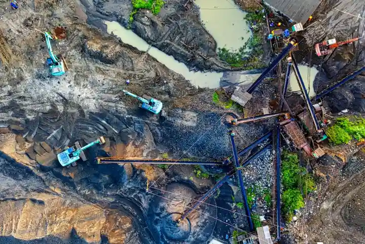
A hydraulic or cable-suspended diaphragm wall grab is the primary tool for mining-site cutoff walls and rectangular pit shafts, reaching 20 to 80 m depth in stiff alluvium and weathered rock, with standard panel thickness typically 600 to 1200 mm [S2]. Mining projects diverge from urban basement work in three ways: longer panel lengths, higher boulder content, and stricter verticality on shaft envelopes.
For tailings dam cutoffs and open-pit dewatering barriers, the grab competes with hydromill cutters, while cable-grab kelly rigs remain the workhorse for rectangular ventilation and production shafts because the rectangular plan suits the mining dump truck muck-handling cycle downstream [S1][S2].
Three Grab Variants and Their Mining Niche
Hydraulic rope-suspended grabs (also called diaphragm wall grabs) typically deliver 80 to 200 kN closing force at the jaws and work panel widths of 2.4 to 4.0 m, suiting soft alluvium, clay, and weathered rock above roughly 40 to 50 m depth where overburden is stable under bentonite slurry [S1][S2]. Cable-suspended kelly grabs add a rigid leader for verticality control on shafts, holding verticality tolerance inside roughly 1:300, which matters where a production or ventilation shaft must be plumb for cage guides.
Hydromill (cutter) rigs are the third option: they mill both sides of a panel simultaneously with reverse-circulation cutters, reach 80 m+ in hard rock, and pair with grabs for pilot-and-pass excavation. For mining cutoff work in dam foundations, diaphragm wall cutoff barriers are specified from 20 to 80 m deep depending on soil and rock conditions, with panel thickness, slurry density, and joint geometry set by the permeability target rather than the structural load alone [S2].
Selection Criteria Mapped to Mining Ground Classes
For tailings dam cutoffs, panel length is normally 2.5 to 4.0 m, panel thickness 600 to 1000 mm, and the target hydraulic conductivity for a soil-bentonite or concrete diaphragm is 1 x 10^-7 cm/sec where full hydraulic isolation is required [S2]. In mine-shaft envelopes the same grab must hold 1:200 to 1:300 verticality over 30 to 60 m of depth, which is why a kelly-guided rig is preferred over a free rope grab on shaft work [S1].
A simple decision tree for mining: (1) soft to medium alluvium, depth under 40 m, low boulder count: standard rope-suspended hydraulic grab, 80 to 120 kN closing force, 2.4 to 3.0 m panel; (2) weathered rock, 40 to 60 m, with cobbles and boulders: heavy rope-suspended grab with 150 to 200 kN closing force plus chisel teeth, or pilot-and-pass with a hydromill on the primary pass; (3) hard rock below 50 m or mixed-face shafts: hydromill as primary, grab for cleaning and rectangular corner cuts. Standard soil-bentonite slurry trench cutoff walls are specified to a maximum hydraulic conductivity of 1 x 10^-7 cm/sec when the wall is the sole seepage barrier, which sets the slurry plant's bentonite dosing accuracy, not the grab spec directly [S2].
Slurry Plant, Tremie Concreting, and Throughput Coupling
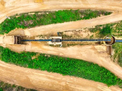
The grab is only one node in the system: bentonite or polymer slurry mixing, desanding, tremie concreting, and wall-head trimming must all match the excavation rate. Slurry trench walls reach depths of 10 to 50 m in soft to medium soils, while diaphragm wall cutoff barriers extend from 20 to 80 m deep, and the choice between rope grab and hydromill shifts the daily output from roughly 50 to 150 m² of panel area on a rope grab to 80 to 200 m² on a mid-size hydromill in similar ground [S2].
For tremie concreting, uninterrupted placement and correct tremie-pipe embedment are decisive for wall integrity, so the concrete plant must keep a head difference between slurry level and groundwater within the spec the bentonite filter cake was designed for [S1]. On remote mining sites this often means twin colloidal mixers with 20 to 40 m³/hr throughput and a desander capable of cutting sand content below 3 to 5 percent before the slurry re-enters the trench, otherwise grab advance slows and panel rework climbs.
Tolerances, Monitoring, and Shaft Geometry
Verticality, panel length, and panel thickness are checked with inclinometers, calipers, and depth gauges, with deviations kept within the project's specified tolerance band; for shaft envelopes this is typically inside 30 to 50 mm lateral drift over 50 m of depth, while for dam cutoffs the tolerance can be looser (1:150 to 1:200) because the wall is a hydraulic element, not a structural lining [S1]. Slurry density, viscosity, and sand content are monitored continuously because the filter cake is what keeps the trench open between grab cycles, and any breach shows up as panel sloughing at the next bite.
For deep foundation-pit work adjacent to existing mine infrastructure, instrumentation tracks wall deformation in the weak soil layer, with recent digital design and safety-assessment studies reporting diaphragm wall deformation capture accuracy of 97.45% in weak soil layers, using a 3 mm displacement threshold to define the deformation-sensitive area (H Huang, 2026) [S3]. That 3 mm figure is useful as a trigger for adjacent-shaft or processing-foundation protection, not as a pass/fail for the wall itself.
Comparison: Grab vs Hydromill vs Kelly Rig on Mining Sites
On capital cost, a rope-suspended hydraulic grab rig is the lowest of the three, a hydromill the highest, and a cable kelly rig sits between them; on daily panel output in soft ground the rope grab is competitive, but in hard rock the hydromill pulls ahead because it mills rather than rakes. On verticality, the kelly rig wins for shaft work, the rope grab is acceptable for linear cutoffs, and the hydromill needs post-excavation trimming of the panel edges with a separate grab pass to clean corners [S1][S2].
On slurry management, all three variants run on the same bentonite plant, but the hydromill generates more fines and demands a larger desander; on site footprint, the rope grab is the most compact and suits confined terraced benches on a pit wall, while a hydromill needs a level pad and crane access for cutter changes. For mixed mining projects that include both dam cutoff and shaft work, the gearbox and drivetrain selection logic used in heavy rotating equipment applies in spirit to the grab's hydraulic power-pack sizing, where torque, flow, and continuous-duty thermal limits matter more than peak pull.
Limitations and Failure Modes Specific to Mining
Rope-suspended grabs lose verticality in loose gravel and where cobbles jam the jaws, which is why a chisel-tooth or boulder-breaker option is specified above 40 m depth in glacial or colluvial mining terrain. Hydromills stall on steel inclusions (old sheet pile, remnant rail, abandoned casing), and recovery requires switching to a grab or a down-the-hole hammer, adding 1 to 3 days per obstruction. Cable kelly rigs are limited by leader length, so any shaft deeper than 50 to 60 m needs a stage-excavation plan with platform relocation. [S2]
Wall integrity failures on mining cutoffs typically trace back to slurry mismanagement (density drift above 1.15 to 1.20 g/cm³, sand content above 5%), tremie-pipe lift during concreting, or stop-end joint defects, rather than to the grab itself; remediation usually means joint grouting or a secant-pile supplementary wall, both of which inflate cost and schedule [S1][S2].
Sourcing, Standards, and What to Verify at Tender
Verify at tender: panel length, thickness, depth band, ground class (SPT N-value, boulder frequency, UCS of rock if present), target verticality, target permeability (1 x 10^-7 cm/sec for full hydraulic isolation), slurry plant throughput, tremie concrete supply rate, and monitoring scope (inclinometer spacing, frequency, and reporting). Slurry trench cutoff walls have been used for over 70 years to control groundwater flow and seepage through dams and levees, so the technique is mature, but the equipment and slurry specifications must be matched to the ground and the wall's role, whether load-bearing, sealing, or both [S1][S2].
For adjacent construction-method context, the selection logic for diaphragm wall grabs on road projects overlaps with mining cutoffs on the panel-geometry and slurry side, while the piling and carrier selection logic used in landfill pile-driving carries over to kelly-rig shaft work. Track going forward: the grab's closing-force class relative to the rated boulder size in the ground investigation report, the slurry plant's desander capacity in m³/hr, and the tremie-pipe embedment log against the spec, because those three numbers are where most mining cutoff walls succeed or fail.
Component reference pages worth checking: diaphragm pump.