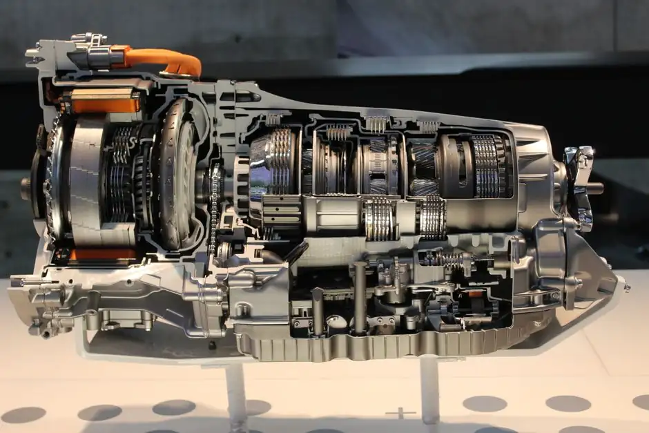
A wind turbine gearbox selection problem is, at its core, a torque-stepping problem: the rotor delivers low-speed, high-torque input (5–20 RPM) that must be raised to the 1500–1800 RPM band a standard generator needs, and the chosen drivetrain topology determines efficiency, mass, service interval, and 20-year fatigue life [S8][S10].
Replacement is the fastest-growing slice of that market. The global wind turbine gearbox market was valued at USD 25.69 billion in 2025 and is forecast to reach USD 45.48 billion by 2033, a 7.4% CAGR, with replacement demand overtacing new-build demand by the end of the period as the existing fleet ages [S1]. The reference for engineering choices is the IEC 61400-4 gearbox standard, which fixes minimum load distribution factors and governs gear-tooth rating for utility-scale units [S10].
Rotor-to-generator ratio: where 4:1 and 6:1 planetary stages sit
The low-speed planetary stage of a utility-scale wind gearbox typically runs a 4:1–6:1 first reduction, taking the full rotor torque before the parallel helical stages step the speed up to generator input [S8]. This first stage is the highest-torque, most structurally critical gear component in the drivetrain because the compound planet/sun/ring geometry carries every Newton-metre the wind delivers [S8].
Smaller distributed turbines solve the same problem with simpler two-position choices. TESUP, for example, sells a 1:4 High-Wind Gearbox that multiplies generator RPM by 4× in strong winds, and a 4:1 Low-Wind Gearbox that trades speed for torque so the turbine cuts in earlier in light air (2025-08) [S3]. The 1:4 unit is intended for coastal, ridge, and open-field sites; the 4:1 unit targets residential or sheltered installations where start-up torque matters more than peak output (2025-08) [S4].
Single-stage, multi-stage, and epicyclic: when each topology wins
Single-stage gearboxes are mechanically simple, cheaper, and lighter, but they cap the achievable ratio and tend to land in smaller turbines or retrofit kits where the rotor-to-generator step is modest [S9]. Multi-stage gearboxes use two or more reduction stages to reach the higher overall ratios (often 1:80 to 1:120 compound) that utility-scale 3 MW+ machines need, at the cost of more bearings, more lubrication volume, and a longer service train [S9].
Epicyclic (planetary) layouts sit between these two because they deliver high ratios from a coaxial, compact package. For two-stage epicyclic gear trains, the S26EW(N) layout is preferred over S26NW(E) on kinematic simplicity (no hollow shafts), and the three-stage S16NW(E) layout is the strongest choice when mass and ring-gear diameter dominate the design brief [S5]. The general engineering trade-off is clear: more planets and a load-distributing carrier reduce point loads and can extend service life by over 15% in wind duty, but they add manufacturing complexity [S7].
Planetary, helical, and pitch-drive: three jobs inside one nacelle
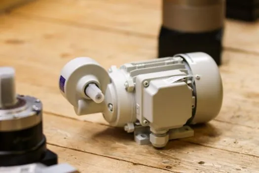
Three different gearbox duties live inside a utility-scale nacelle, and they do not share a spec. The main drivetrain gearbox steps rotor speed to generator speed through the planetary + parallel helical arrangement covered above. The yaw drive gearbox rotates the nacelle to track wind direction. The pitch drive gearbox, mounted at each blade root, turns the blade about its axis to regulate power capture and provide emergency aerodynamic braking [S6].
Pitch drives run in slow, high-torque, high-cycle conditions and fail in characteristic ways: micropitting and grey staining on planet/sun flanks from thin oil film at low speed, often aggravated by inadequate EP additive or surface roughness mismatch above Ra 0.8 µm after grinding [S6]. Specification practice is to demand flank load-carrying lubricant, controlled surface finish, and EP additive packages matched to the slow-speed duty, with full replacement as the default once planet-bearing spalling or ring-gear cracking is observed [S6].
Main-gearbox planetary stage: floating sun, load sharing, 20-year life
The main gearbox's planetary stage is where most of the engineering effort concentrates. A floating sun gear arrangement, where the sun shaft is radially unconstrained and self-centres by equalising tangential forces from all planet meshes simultaneously, is one of the most effective passive load-sharing geometries in production wind gearboxes today, and is a direct response to the load-distribution factors written into IEC 61400-4 [S10].
Fatigue design targets 20-year service life on the low-speed stage, with through-hardened or case-carburised alloy steels, ground or super-finished tooth flanks, and a lubrication circuit sized for the sustained torque the rotor will deliver in the worst 50-year wind [S8]. Bearing selection is the second-line decision: cylindrical roller bearings on the planet carriers and tapered roller bearings on the main shaft are common, with white-etching cracking and axial cracking flagged as the dominant life-limiting failure modes when lubricant cleanliness or alignment drift slips [S8].
Replacement: OEM, aftermarket, upgraded, or custom
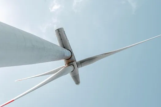
Wind gearbox replacement is now a four-way decision. OEM direct replacements guarantee fit and duty match but cost more and carry longer lead times. Aftermarket equivalents are built to meet or exceed OEM torque, ratio, and load-rating specs at lower cost and shorter lead time. Upgraded replacements add better bearings, improved lubrication, and higher-efficiency gearing. Custom-engineered replacements are specified for retrofit jobs where the original model is obsolete or the turbine has been uprated past its original rating [S2].
The decision pivots on four engineering checks: torque capacity and load rating must match the duty, gear ratio and output speed must align with the generator, mounting and shaft dimensions must match the existing bedplate, and the lubrication and cooling system must be capable at the new operating point [S2]. For offshore sites, corrosion protection is a fifth, non-negotiable check, because salt-air exposure and humidity drive bearing-race pitting and seal failures long before the gears wear out [S2].
Selection criteria compared: small-twin gearbox vs main drivetrain vs pitch drive
Three gearbox roles, three different spec sheets. A small-twin optional gearbox (TESUP class) is defined by a single ratio choice (1:4 or 4:1), 4.5–15 kW peak power, and a cut-in/cut-out trade-off tuned to site wind class [S3][S4]. The main drivetrain gearbox is defined by total ratio (typically 1:80 to 1:120 compound across planetary + helical), torque capacity, IEC 61400-4 load-distribution factors, and a 20-year fatigue life target [S8][S10]. The pitch drive is defined by slow output speed, high hold-torque under load, EP-grade lubricant, and flank finish held to Ra 0.8 µm or better [S6].
The cost axis runs the same direction: small optional gearboxes are commodity-priced accessories, main drivetrain gearboxes are six- to seven-figure capital items with 6–12 month lead times, and pitch drives are mid-cost assemblies sold in sets of three per turbine but with high replacement frequency over a 20-year life [S2][S6].
Failure modes and what they tell the selector

Wind gearbox failure data is unusually clean because the duty is so consistent. Bearing failure is the single most common cause of replacement, followed by gear-tooth wear and fatigue, lubrication breakdown, misalignment, thermal stress, and contamination from moisture or debris [S2]. On the planetary stage specifically, white-etching cracking under rolling contact, axial cracking from thrust loads, and micropitting at the planet/sun mesh dominate the field-failure picture [S8].
These patterns point directly at selection levers. Specifying a flank load-carrying lubricant and holding surface finish to Ra ≤ 0.8 µm addresses the micropitting cluster. Specifying improved sealing, breathers, and offline filtration addresses the contamination and lubrication cluster. Specifying a floating sun gear and load-distributing planetary layout addresses the point-load and life cluster [S6][S7][S10]. For background on how planetary and helical stages are matched to service factor in another heavy industry, see gearbox selection for mining, which applies the same torque-and-duty logic to a different load profile.
Standards, sourcing, and where the market is heading
Engineering reference for wind gearboxes is IEC 61400-4, which sets minimum load distribution factors and tooth-rating rules; for materials and fatigue it is the ISO 6336 family of gear-strength standards; for lubrication it is ISO 12925 and OEM-specific EP additive qualifications [S10]. The market trajectory is unambiguous: USD 25.69B in 2025, USD 45.48B by 2033, 7.4% CAGR, with replacement outpacing new-build from the late 2020s as the global fleet crosses its first major mid-life overhaul wave [S1].
Two trackable signals to watch through the rest of 2026 and into 2027: (1) the cadence of multi-MW offshore turbine orders, which sets the next main-gearbox demand pulse, and (2) the published IEC 61400-4 maintenance and inspection guidance updates, which tend to flow into aftermarket replacement specs within 12–18 months of release. The pitch and yaw segments, often overlooked next to the main gearbox, are where the highest unit volumes will ship because every turbine carries three pitch drives and one yaw drive, and each has a shorter mean time between replacement than the main gearbox.
Detailed specification references: gearbox, power cable, and power distribution.