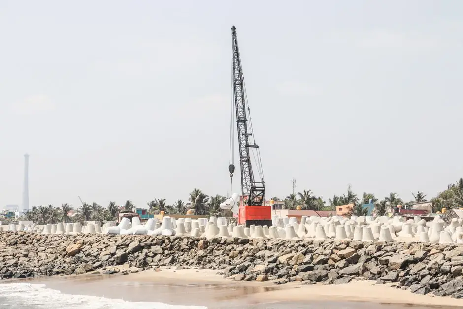
For road and bridge approaches crossing soft alluvium or high-water-table urban corridors, the diaphragm wall grab is the workhorse excavator for 400 mm to 1200 mm thick, 15 m to 40 m deep panels [S1][S2].
Selection is driven by panel geometry, soil class, and the verticality tolerance the road design imposes on the permanent wall; machine type (single-clamp, rope-suspended, hydraulic crawler, or rotary cutter) follows from those three inputs rather than brand preference [S1][S2].
Selection Criteria Tied to Road Project Geometry
Diaphragm wall panels for road schemes typically run 2.8 m to 6.0 m long, 600 mm to 1000 mm thick for underpass cut-and-cover, and 1000 mm to 1200 mm thick where the wall also acts as a bridge abutment or pile cap [S1][S2].
For road projects where the wall doubles as permanent structure, watertightness of joints, verticality and position tolerances, adequate concrete cover, and reliable structural continuity at connections are the four performance criteria the grab must enable [S2]. Verticality is normally held to 1:200 to 1:300 over panel depth; that tolerance dictates whether a guided hydraulic grab or a free-suspended rope grab is acceptable.
Guide walls at the surface are mandatory; they confine the upper trench zone, align the grab, and set the reference plane the road alignment depends on [S2].
Soil and Groundwater Conditions
Support fluid, typically bentonite or polymer slurry, maintains trench stability between excavation and tremie concreting, and a stable filter cake on the trench walls is what keeps the road corridor open during the panel cycle [S2].
Slurry density, viscosity, and sand content must be monitored continuously: deviating slurry properties are the single most common cause of trench collapse in soft alluvial road sites, and they dictate the rate at which the grab can be cycled [S1][S2].
Head difference between slurry level and groundwater is one of the decisive variables for wall integrity; a minimum positive head of roughly 1.0 m to 1.5 m above the standing water table is standard practice on diaphragm wall sites [S2].
Grab Type Comparison for Road Works
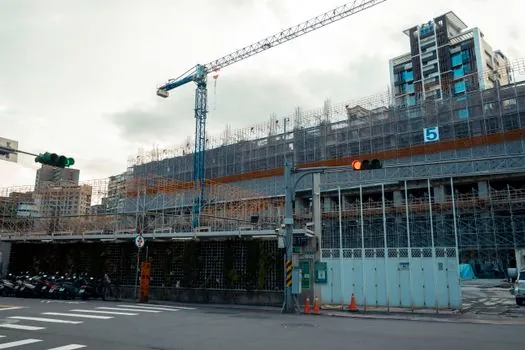
The four configurations contractors actually compare on a road bid are: single-clamp hydraulic grab, rope-suspended grab, heavy hydraulic crawler grab, and trench cutter (hydrofraise). A side-by-side against the criteria that matter on a road site reads as follows. [S1]
Single-clamp hydraulic grab: simplest arrangement, suited to standard trench excavation in cohesive soils and for foundation projects, retaining walls, and underground structures where ground conditions are favourable [S1]. Depth capability is usually limited to roughly 30 m before cycle time and verticality drift become uneconomic [S1].
Rope-suspended grab: uses a crawler or crane carrier with a Kelly-less rope grab; lower mobilisation cost, suitable for shallower retaining walls along road embankments and noise-barrier footings where panel depth is under 20 m [S1].
Heavy hydraulic crawler grab (telescopic kelly or rigid kelly): the default for urban road underpasses and metro cut-and-cover; handles 30 m to 60 m panels, larger grab buckets (800 mm to 1200 mm wide), and on-board inclinometers for verticality control [S1][S2].
Trench cutter (hydrofraise): rotary cutting drums mounted on a kelly, used where soil is too hard or too deep for a grab, or where verticality tolerance is tighter than 1:300; the cutter mills the soil while reversing slurry, then lifts cuttings to a desander [S3]. Specified for road schemes that cross boulder beds, weathered rock, or where adjacent structures impose stricter deformation limits [S3].
Who the Grab Is For, and Where It Is the Wrong Tool
The grab is the right tool for cohesive soils, granular soils above the water table, and mixed urban fills where the panel can be held open with bentonite or polymer slurry long enough to clean, cage, and pour [S1][S2]. For deep road underpasses, bridge abutment walls, cut-and-cover metro sections, and tunnel approach retaining walls, the grab-based method is the industry default [S1][S3].
It is the wrong tool where the soil profile includes large boulders, massive rock, or karstic voids, and where panel depth exceeds what the kelly and grab mass can cycle within an 8- to 12-hour shift; in those cases the trench cutter takes over even at higher unit cost [S3]. For very shallow road-side service trenches under 6 m, a long-reach excavator with a trenching bucket is typically more economical than mobilising a full diaphragm wall spread.
Execution Tolerances, Monitoring, and Cycle
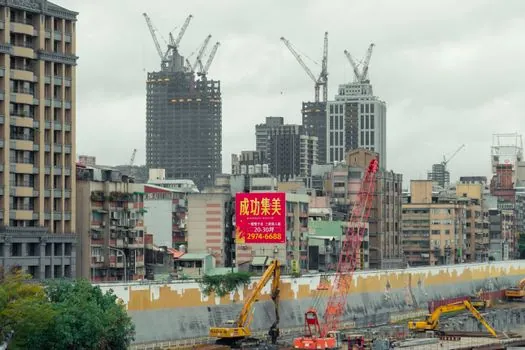
Geometry control on a road scheme is verified with inclinometers mounted on the grab, caliper checks of panel width, and depth measurements against the guide wall reference; deviations are recorded against the specified tolerance envelope [S2].
The panel cycle is: setup and guide wall construction, excavation under support fluid, cleaning and end-profile check, lowering the reinforcement cage with spacers, tremie concreting, and finally jointing to the adjacent panel via stop-ends or water bars [S2]. Uninterrupted tremie placement, correct embedment of the tremie pipe, and maintaining the required slurry-to-groundwater head difference are the three execution variables that decide wall integrity and homogeneity [S2].
After pit excavation, the wall head is trimmed to target elevation with low-noise, low-vibration tools such as concrete pulverizers or hydraulic rock and concrete splitters, which produce clean interfaces between the diaphragm wall and the bracing, slab, or capping beam the road deck sits on [S2].
Limits, Failure Modes, and Sourcing
The two failure modes that bite road projects are trench collapse during the open phase and panel out-of-tolerance verticality; both are driven by slurry management and grab guidance quality, not by the carrier's nameplate power [S1][S2]. Specifying a grab without an on-board inclinometer, or accepting a rope grab where the design calls for 1:250 verticality, is a procurement decision that surfaces as rework during wall head trimming.
Relevant equipment families to cross-reference when building the spec sheet are listed in the construction tools encyclopedia entry, with platform-mounted grabs, cutters, and the slurry desanding plant all covered as a system rather than as standalone machines [S1][S2].
For site plant, a road contractor typically pairs the grab with a diaphragm pump spread for slurry circulation and a service crane for cage lifts; both items belong on the same mobilisation list as the grab itself [S1][S2].
Trackable signals over the next planning cycle: slurry density and sand-content logging becoming a contractual submittal rather than a contractor option, and crawler grabs with integrated digital verticality logs replacing paper inclinometer charts on tier-one road underpass projects [S2][S3]. On the equipment side, the boundary between heavy hydraulic grabs and small-format trench cutters continues to narrow as cutter kelly lengths stretch into the 60 m to 80 m range, which is the single procurement variable worth watching for deep urban road schemes in the next 12 months [S1][S3]. For adjacent spec work on road-building plant, see the pile driver selection map for landfill operations and the gearbox selection spec map for material handling conveyors, which cover carrier-class and drive-train decisions that often share a supplier with the diaphragm wall spread.