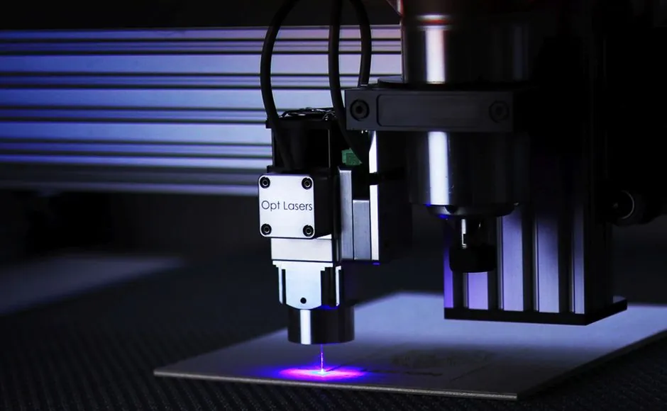
A CNC digital twin is a live virtual replica of a machine tool, its control logic, kinematics, and cutting process, used to predict chatter, track flank wear, and compensate geometric and thermal error before parts go out of spec [S2].
The technology moved from academic prototype to production-line tool between 2024 and 2026: NIST published a CNC digital-twin build reference in December 2024, peer-reviewed surveys in 2025 catalogued 464 papers and reported 80+ publications in 2024 alone, and a March 2026 industrial report documented error reductions near 50% on deployed cells [S1][S5][S7].
What a CNC digital twin actually contains
A CNC digital twin is more than a 3D CAD model, it is a five-layer stack: physical asset, sensor layer, data-fusion layer, model layer, and service layer that closes the loop back to the controller [S4]. The model layer runs the kinematic chain, the thermodynamic model of the spindle and ballscrews, the chip-formation force model, and a wear-progression model updated from in-cut signals.
NIST's December 2024 build reference frames the whole stack against ISO 23247, the manufacturing digital-twin standard, so that each layer has a defined data schema, communication protocol, and update cadence [S1]. The same architecture is used whether the twin runs on a controller edge PC, a cell-level server, or a cloud instance, the difference is latency and model fidelity, not the data model.
The five functions the twin must perform on a CNC, drawn from the 2025 Journal of Manufacturing Systems review: real-time error identification, data-driven multi-source error modelling, causal traceability, predictive error estimation, and closed-loop adaptive compensation [S3]. If a deployment is missing any of the five, it is a monitoring dashboard, not a digital twin.
How chatter and tool wear are modelled today
Chatter prediction in a twin combines a stability-lobe map (spindle speed vs. depth of cut) with a regenerative-wear coefficient that grows as the tool ages, so the safe depth-of-cut envelope shrinks over the cut, not just between parts [S3]. The wear model typically takes flank-wear width VB as the state variable and fuses cutting force, acoustic emission, and vibration RMS through a Kalman or particle filter to update VB at 1 kHz or higher [S4].
Tool-wear remaining-useful-life (RUL) models in 2024-2025 papers most commonly use a CNN-LSTM or Transformer trained on multisensor windows; bibliometric analysis of 464 Web of Science papers shows deep-learning RUL estimators are the dominant published method, displacing the older empirical Taylor-tool-life equation in research-grade implementations [S5]. Sensor fusion of accelerometer, AE, and spindle current with a CNN backbone has been shown to detect insert breakage in time to retract the tool before a crash [S4].
Thermal error, which is geometric drift of the spindle axis as the machine warms, is handled in the same twin through a thermally-coupled FEA or a grey-box RC network fed by temperature sensors in the spindle housing and ballscrew nuts; compensations are then written as axis-offset tables to the controller [S3].
Selection criteria: when a twin pays for itself, and when it does not
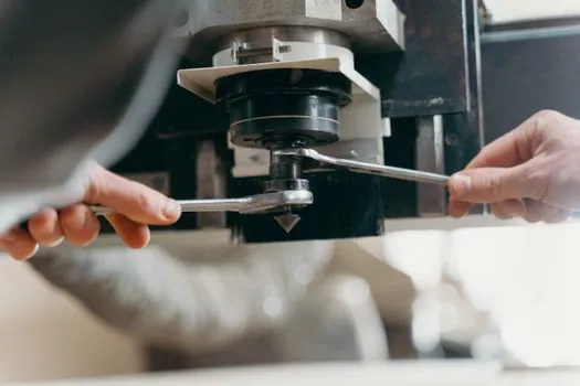
The selection signal is part-mix and tolerance, not machine value. A job shop running high-mix, low-batch work with tight tolerances benefits most, because the twin validates NC programs virtually before the first chip is cut, eliminating trial cuts on the physical machine [S2]. A high-volume dedicated cell with one part running for months has less to gain, the process is already stable, and a closed-loop in-process gauging system may give a better ROI than a full twin.
A 2026 industrial case study reports that deployed twins in a UK tier-1 supplier cut geometric and thermal error roughly in half on a 5-axis machining centre, with the saving coming from virtual proving of NC code plus live compensation, not from faster spindles or new tooling [S7]. The same report stresses that the data ingestion, MTConnect or OPC UA on a controller edge PC, is the rate-limiting step; if the machine does not expose live feeds the twin cannot update in real time.
Decision criteria in practice, ordered by weight: (1) is the part mix variable enough that proving on the machine costs you capacity; (2) does the tolerance band sit in the 5-20 micrometre range where thermal and dynamic error dominate; (3) does the controller expose MTConnect, OPC UA, or Focas for live data; (4) is there a team that can maintain the model, an unmaintained twin decays back to a dashboard within a year.
Comparing the three mainstream deployment patterns
There are three patterns in use, and they are not interchangeable. Pattern A, controller-resident virtual proving, runs G-code through an NC kernel (e.g. Siemens Run MyVirtual Machine, Heidenhain TNC, Fanuc NCGuide) on an office PC, no live sensor link, used for first-time-right and crash detection before the program is sent to the shop floor [S2]. Pattern B, edge digital twin, adds a live MTConnect/OPC UA link and runs a reduced-order model on a cell-level industrial PC, used for in-process compensation and tool-wear tracking. Pattern C, cloud or cluster twin, runs high-fidelity multi-physics models and fleet-level analytics, used for RUL prediction across many cells and for what-if scheduling.
Pattern A is cheapest (USD 5k-50k range for software plus integration) and pays back in job shops; Pattern B sits in the USD 50k-250k range including sensors and edge hardware; Pattern C is a multi-year programme and only makes sense above 20-30 connected machines [S3][S7]. Selection is driven by tolerance, part-mix variability, and controller openness, not by brand loyalty. For a deeper read on where high-fidelity modelling is worth the cost, see the analysis of Digital Twin fidelity levels.
Standards, schemas, and what to specify in a purchase
The reference architecture is ISO 23247, with the NIST December 2024 build providing a worked example of how each of its four parts maps to a CNC cell [S1]. MTConnect and OPC UA are the two data-exchange protocols in widespread use; UMAC (UMAC MTConnect) and the OPC UA Companion Specification for Machine Tools are the machine-tool-specific bindings. For cutting-process data the IEEE 1451 family of smart-sensor standards and the ISO 13373 series for condition monitoring cover vibration-based tool-condition monitoring.
On the model side, ISO 23247 Part 2 defines the reference architecture, Part 3 the digital-twin concept and models, Part 4 the data exchange formats, so a procurement spec can ask for ISO 23247 conformance rather than describing the schema line by line [S1]. Buyers should also require MTConnect or OPC UA streaming at 100 Hz or higher for spindle current and axis feedback, AE and vibration channels at 10 kHz+ for chatter detection, and a documented API for model update [S4]. The architecture reference is useful background when writing such a spec.
Real failure modes and limitations engineers should know
Model drift is the dominant failure: a thermal or wear model calibrated on a warm machine in January performs differently in August when the shop HVAC is on full blast, the controller will then over- or under-compensate [S3]. The fix is a periodic re-calibration pass against a reference artefact (e.g. a square test cut, a laser interferometer sweep) and a logged drift metric, not a one-time commissioning.
Data-fusion timing is the second failure: chatter energy sits in the 500-2000 Hz band for steel milling, and if the acquisition rate is below 4 kHz with anti-aliasing the model will see a smoothed signal and miss the regenerative peak [S4]. Procurement specs that accept 100 Hz "vibration" channels are buying a dashboard, not a twin.
A third limitation is the controller-to-model round trip latency; if the compensation command takes longer than one servo cycle (typically 1-2 ms on a modern CNC) the twin is observing, not controlling, and chatter suppression is limited to operator advice rather than live axis correction [S3]. For practical guides on what a digital twin deployment looks like end-to-end, the architecture reference walks through the layers from sensor to dashboard.
Signals to track over the next two quarters
Three signals are worth watching: (1) publication of the ISO 23247 implementation profiles for subtractive manufacturing, which would give procurement a sharper conformance target than the current four-part reference; (2) controller vendors (Siemens, Fanuc, Heidenhain, Mazak) shipping native MTConnect or OPC UA bindings on entry-level CNCs, which would lower Pattern A cost by removing the Focas or proprietary adapter layer; (3) shop-floor case studies quantifying dollar-per-part savings rather than percentage error reduction, which is what a finance team needs to sign off a Pattern B or C deployment. [S2]
The arc from the NIST 2024 reference through the 2025 review literature to the 2026 industrial deployments shows the technology is past the proof-of-concept stage on 5-axis cells with tight tolerances, and the open question is no longer whether a twin reduces error, but which deployment pattern matches a given part-mix and controller stack.
Component reference pages worth checking: digital multimeter, digital panel meter, and checking and testing apparatus.