Directed and circular vibration exciters produce different drum trajectories, so selection depends on traction, compaction pattern, operating mode, and exciter architecture.
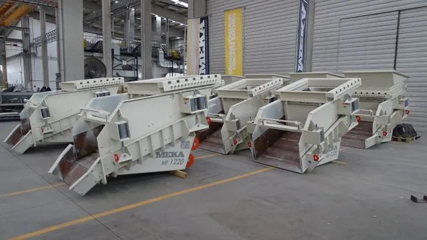
Conventional screen exciters generally use an eccentric mass rotating about the exciter shaft, and the stroke type can be circular, linear, or elliptical depending on exciter placement and operational synchronization.
What the two exciter types physically do
A conventional exciter includes a housing, bearing, shaft, and eccentric mass; rotation of the eccentric mass generates the vibration [S3]. Circular motion produces a repeating path whose direction changes continuously, allowing the drum or screen to receive energy in multiple directions during each cycle.
The controlled mechanical exciter described in S2 uses two unbalanced shafts, and its generated excitation depends on the rotation angle of the movable unbalanced masses relative to their initial positions. A roller design may support circular or directional vibration with continuously adjustable vibration amplitude and force [S6]. A controlled mechanical exciter with two unbalanced shafts is modeled as a circular translational-vibration system whose excitation depends on the rotation angle of the movable unbalance masses relative to their initial positions [S2].
The practical distinction is the force vector delivered to the drum, not simply the presence of an eccentric shaft. Circular excitation repeats a closed trajectory. Directional excitation creates a biased or preferentially directed vibration pattern. The latter adds a controlled vector to the circular component, allowing the machine to use vibration for movement as well as material processing.
Decision criteria for roller applications
Select a circular exciter when compaction quality, screening action, or uniform energy distribution is more important than directional propulsion. Circular vibration supplies continuously changing force directions, which supports tumbling and repeated contact with the processed material [S3]. A roller fitted to a road roller is therefore a natural application for circular excitation when the objective is densification across the drum width.
Select a directional exciter when the roller must climb gradients, move through cohesive material, or concentrate vibration ahead of or behind the drum center. This arrangement is less suitable when the specification requires an isotropic vibration field, since directional bias reduces symmetry and can create uneven working coverage.
Use three criteria in sequence: first, identify the required force direction; second, check whether the drum motion is circular, linear, or elliptical; and third, verify whether amplitude and frequency must change during operation. Exciters are not interchangeable merely because both use rotating unbalanced masses. Their mounting, phase relationship, counterweight arrangement, and drive controls determine the resulting trajectory [S3].
Explicit comparison of the main options
Vibration rollers can use circular or directional vibrations with continuously adjustable vibration amplitude and/or vibration force. On material interaction, circular motion repeatedly changes force direction and promotes tumbling, whereas directional motion emphasizes motion and compaction along one working line [S3].
On adjustment and control, circular systems can use variable exciting power, and directional systems can provide continuously adjustable amplitude and force, but the required mechanism differs by design [S4][S6].
The compact decision matrix is therefore straightforward: use circular excitation for uniform, omnidirectional compaction; use directional excitation when propulsion or directional energy delivery is the primary requirement; use an adjustable controlled exciter when operating load changes require active amplitude regulation. A vibration-compaction specification that names only “high amplitude” does not resolve this choice because it omits the trajectory requirement.
Applications suited to directional vibration
Directional vibration is appropriate for self-propelled rollers traveling on weak or steep ground, especially where wheel slip would waste engine power or disrupt the working surface. Patentable roller arrangements explicitly cover self-propelled vibration rollers using circular or directional vibration with adjustable amplitude and force [S6]. The directional system is therefore not merely a laboratory vibration mode; it is a propulsion and compaction architecture.
The useful feature is the deliberate relationship between drum force direction and travel direction, rather than the maximum nominal force alone.
Planetary and asymmetrical exciter research links the supplied vibration energy with disturbing force and sealing capacity, but it also shows why trajectory geometry matters. One planetary design uses a race track formed from circular and elliptical sections, with transition curves required to preserve tangent continuity and equal curvature at the junctions [S5]. Abrupt changes in curvature create a centrifugal-force jump, so directional or compound trajectories require controlled transitions rather than simple geometric steps.
Limitations, failure modes, and operating constraints
Directional excitation can create uneven compaction, directional stress, and frame loads if the phase or amplitude is poorly matched to the material. Circular excitation can create higher roller wandering, energy use, and abrupt movement if the drum trajectory is not controlled. Analytical work on horizontal oscillating vibration shows that drum movement can become non-uniform during one exciter revolution, producing an oscillating forward motion rather than constant travel [S8].
Conventional unbalanced exciters have low energy efficiency and difficult starting conditions because installed mechanical capacity is selected with margin over the process load. Their mass-produced versions also generally do not permit operating adjustment of the disturbing force [S1]. This limitation favors frequency-controlled, closed-loop drives when changing material conditions require different amplitude or force.
Electromagnetic exciters allow amplitude control by changing electrical power, but they consume more material [S1]. Unbalanced machines can instead be adjusted across a frequency range, with a closed-loop drive compensating for process load and crossing resonance with a minimum disturbing force [S1]. The design trade-off is therefore capital and mechanical complexity against operating flexibility.
Bearings, housing, shaft, belt drive, and unbalance retention all remain mechanical constraints. Screening exciters commonly use self-aligning double-row spherical roller bearings, with bearing count determined by housing and load capacity [S3]. A roller specification should also distinguish fixed amplitude, adjustable amplitude, adjustable frequency, and adjustable force because these are separate operating functions.
Procurement and verification checklist
Request the drum trajectory, not merely the exciter type: circular, linear, elliptical, or directional. Obtain the operating frequency range, maximum centrifugal force, amplitude adjustment method, permitted eccentric-mass configuration, and direction of the principal force vector. A two-shaft circular translational exciter is defined by the angular position of its movable unbalanced masses, making that positional relationship a core procurement item [S2].
Ask the supplier to demonstrate the mode transition and recovery after a starting or operating-load change. In an adjustable four-unbalance system, a frequency-converter setting change affects induction-motor angular velocity through defined transient behavior, and the physical experiment used to refine the model confirms that response must be treated as a controlled dynamic process [S1].
Check the drum, frame, bearings, and drive against the directional load path rather than rated exciter force alone. For planetary or elliptical trajectories, document curvature continuity at every transition [S5]. For the complete machine, compare the selected roller configuration with the operating class of an asphalt paver where paving train movement and compaction coordination are relevant.
For most soil and asphalt compaction duties, specify circular vibration unless a measurable propulsion or directional-loading benefit justifies the added control complexity. For self-propelled rollers that must move through resistant material, specify directional excitation and verify the force vector under loaded, unloaded, climbing, and stopping conditions.