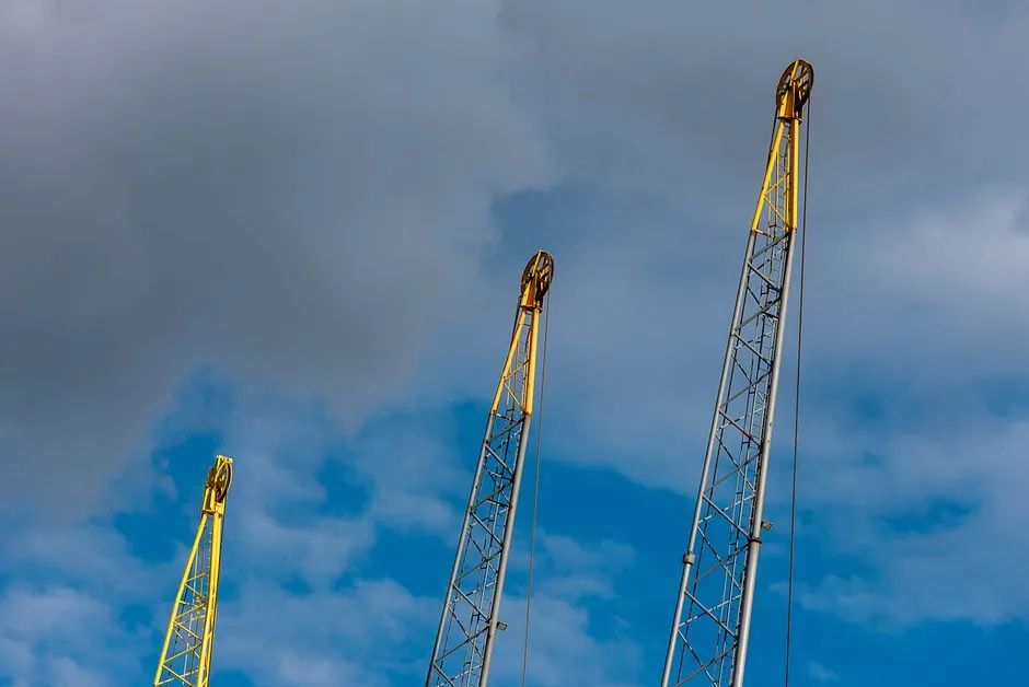
A dynamic-compaction crane must be configured so its rated capacity covers the 15–40 t tamper, lifting hardware, and controlled free fall; the tamper is typically dropped from 10–40 m [S2][S3].
The counterweight is part of the lifting-system stability envelope, while the dynamic compactor must also deliver repeatable drops, withstand impact loading, and keep the crane within its manufacturer’s load chart.
Counterweight sizing starts with the full lifting duty
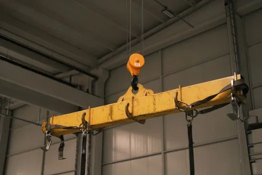
Dynamic compaction uses a heavy steel tamper, typically 15–40 t, released from a height of 10–40 m [S2]. The crane therefore carries the tamper mass, lifting attachments, rope or free-fall system, and any handling frame through the full lift cycle.
Counterweight calculations should begin with the tamper mass and apply the manufacturer’s load-chart deductions for the boom, hook block, lifting equipment, and configured radius. A common sizing error is to check only the static weight of the tamper at the shortest radius, because the operating radius is fixed by the compaction grid and can place the load near the crane’s stability limit.
A verified example used an 18.2 t, 1.5 m diameter tamper, a 30.2 m high-energy drop, and a 3 m by 3 m rectangular grid [S5]. For that arrangement, the crane configuration must account for six high-energy drops per point, followed by an ironing pass using three drops from 7.2 m on the same grid [S5].
Energy and drop height are not crane-capacity substitutes
Drop energy is the product of tamper weight and drop height, but impact energy does not determine counterweight by itself. The lifting system must remain stable while raising the mass to the selected height, and the crane must have sufficient structural and lifting capacity for the complete suspended load [S2][S3].
Published operating ranges show why the check must be project-specific. Steel weights of 15–40 t are dropped from 10–40 m [S2], while Liebherr describes impact compaction with tamper weights released from heights up to 40 m [S3]. The Rocscience example uses 18.2 t from 30.2 m for the high-energy pass and 7.2 m for ironing [S5].
A practical comparison is therefore straightforward: a 15 t tamper at 10 m, a 40 t tamper at 40 m, and an 18.2 t tamper at 30.2 m represent materially different crane duties [S2][S5]. The two variables that determine impact demand are mass and height, while crane stability depends on radius, boom geometry, attachments, and counterweight configuration.
Choose the crane by load chart, not by maximum drop height
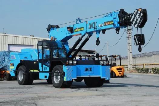
Duty-cycle crawler cranes with free-fall winches and automated crane control are used for impact compaction [S3]. Selection should remain tied to the machine’s rated capacity and configured working radius at every stage of lifting, including the initial lift, free-fall release, tamper recovery, and movement to the next grid point.
Crane selection for this method differs from ordinary pick-and-carry work because the operation involves repeated high-load lifts followed by rapid mass release. The stated 40 m maximum tamper-drop height is not a universal crane-capacity figure; it is a method capability tied to the selected equipment and configuration [S3].
The counterweight arrangement should also be checked for operating restrictions created by the compaction layout. This can force a wider working radius than the initial layout drawing implies.
Dynamic compaction suits granular ground, not every soil
Dynamic compaction is most effective in permeable, granular soils, while cohesive soils can absorb the energy and reduce the effectiveness of the treatment [S2]. The verification example concerns dynamic compaction of a landfill and includes sections on post-improvement SPT and elastic modulus.
That soil limitation affects crane planning indirectly. If the ground cannot dissipate repeated impacts efficiently, additional drops may not deliver proportionate improvement. A 1995 reference states that 7–15 high-level-energy drops are normally applied at each drop point, and that calculations significantly below 7 or above 15 should be reconsidered [S1].
Dynamic compaction is not suitable for routine shallow compaction where a smaller, repetitive tamper can complete the work without the crane and foundation loads associated with a high-energy drop. It is also a poor automatic choice for sensitive cohesive deposits, saturated ground with slow pore-pressure dissipation, or sites where vibration limits prohibit the work [S2].
Site constraints can govern the usable drop energy
Noise, airborne gusts, and vibration are additional environmental constraints, particularly in developed areas [S2].
Near-surface sinkholes can be exposed and remediated by high-energy drops before surface construction, but crater formation is an expected part of the process [S6]. Liebherr describes refilling the created craters with suitable material and further compaction where required [S3].
Groundwater also changes the execution method. The documented impact-compaction approach uses a crane with a free-fall winch to drop a heavy tamper weight onto the ground. These variants must be treated as different crane, access, and counterweight problems rather than folded into a single equipment specification.
Ground treatment quality still needs field verification
High-energy drops do not replace testing. The Rocscience verification example evaluates depth of improvement, applied energy per unit area, post-improvement SPT N, elastic modulus, crater depth, induced settlement, and peak particle velocity [S5]. Counterweight selection is therefore one part of a broader quality-control process, not the sole evidence of ground performance.
The empirical depth relationship uses the square root of tamper weight multiplied by drop height, with a soil-dependent coefficient. Published values place the coefficient between 0.3 and 0.7, with lower values for finer-grained soils [S2]. For the semipervious landfill example, a coefficient of 0.35 with an 18.2 t tamper and 30.2 m drop produces an estimated improvement depth of 8.2055 m [S5].
Grid geometry also affects applied energy per unit area. Rocscience uses square and triangular equivalent-area factors in its calculation, including 0.867 times the square of spacing for an equilateral triangular pattern [S5]. That makes grid layout, not just tamper and height, part of the crane operating envelope and production plan.
Commission the crane as an integrated work system
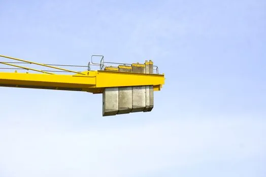
The defensible counterweight requirement is the configuration that keeps every lift inside the crane maker’s load chart at the actual working radius and supports the selected free-fall process. For planning, document the tamper mass, maximum lift height, boom length and configuration, lifting attachments, minimum operating radius, maximum radius, grid dimensions, and counterweight arrangement. [S3]
Two measurable checks should remain open through execution: the actual tamper and rigging mass against the crane load chart, and field ground performance against the specified SPT N, settlement, crater, and vibration criteria [S5]. A third signal is operating stability: repeated free-fall cycles should occur without loss of control, unintended rope unwinding, or operation outside the approved load chart [S3].