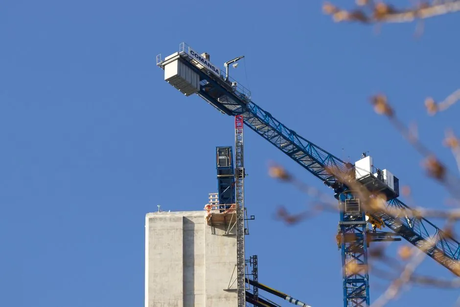
Dynamic compaction commonly drops a 5–20 t hammer from as much as 20 m, while the machine must also withstand ground vibration and boom-rebound impact [S1].
The workable boom angle is not a fixed number: it is the angle supported by the crane load chart after accounting for hammer mass, lifting radius, boom geometry, machine configuration, and the added shock of release.
Dynamic Compaction Operating Envelope
A crawler crane normally drops a 5–20 t hammer from a height of up to 20 m for ground reinforcement [S1]. Duty-cycle cranes used for the same application extend from 30 to 100 t maximum load capacity and from 35.5 to 63.5 m maximum hook height across the listed SENNEBOGEN models [S2].
The dynamic compactor converts hammer potential energy into repeated ground impacts, but the crane handles two distinct dynamic inputs: seismic energy transmitted through the tracks and unloading or rebound force acting at the boom tip [S1]. Ground vibration is concentrated near the impact point.
Boom-tip loading remains a separate concern. Crane overturning and jib fracture were two main crane-failure phenomena, and vibration from the hammer impacting the ground seriously affects crane structural safety and operational stability [S1]. A boom-angle limit based only on the static load chart therefore does not fully characterize high-energy drops.
Why Boom Angle Changes the Limit
At a fixed boom length, increasing boom elevation reduces the horizontal radius and the load moment about the slewing center, allowing a higher permitted capacity. Lowering the boom increases the radius and moment, reducing allowable capacity [S3]. Published guidance illustrates that a crane might lift 50 tons at a 5-metre radius but only 5 tons at a 20-metre radius [S4].
Boom length matters independently. Holding the angle constant, a shorter boom provides a shorter torque path and greater rigidity, while a longer boom has greater flexibility, deformation, and torque loading [S3]. Load charts therefore present separate capacity curves for different boom lengths, with radius or boom angle defining the operating point [S3].
The comparison is direct: a steeper angle generally provides more capacity at the same radius and boom length, while a flatter angle increases radius and reduces capacity. The lower-angle arrangement can still be valid if the load chart shows adequate margin, but it is not the preferred geometry when minimizing impact exposure or maximising reserve capacity.
Static Capacity Versus High-Energy Drops

The crane load chart defines the maximum safe lifting capacity from structural strength, hydraulic performance, and stability design, with capacity varying by boom length, radius, and counterweight configuration [S3]. For a dynamic compactor, the charted suspended load includes the hammer, lifting frame, and any connected tackle, not merely the nominal hammer mass.
Release creates a short-duration shock condition rather than a normal static lift. When the crane suddenly releases the heavy hammer, its impact on the ground generates vibration that seriously affects the crane's structural safety and operational stability [S1]. That mechanism makes boom-tip condition and the condition of the anti-backward-tilting device part of the operating decision, not secondary inspection items.
No universal angle covers every crane. An angle can be acceptable under a 5 t hammer at a short radius and unacceptable under a 20 t hammer at a greater radius or longer boom. The defensible method is to enter the complete lifted mass, radius, boom length, counterweight, and machine configuration into the manufacturer chart, then retain a separate margin for the drop duty cycle.
Selecting a Safer Working Geometry
Select the operating point from the load chart first, then compare it with the intended hammer and drop height [S1][S3]. The load chart identifies the safe static limit, while the drop assessment examines whether repeated shock can fatigue the boom tip, anti-backward-tilting system, or machine structure [S1].
Duty-cycle crane dimensions provide a useful screening range rather than a universal angle rule. The SENNEBOGEN 690 HD and 630 E each have a maximum load capacity of up to 30 t and a maximum hook height of up to 35.5 m [S2]. These are envelope data, not confirmation that every machine can perform a 20 m drop at its maximum rated load.
Site layout also affects the choice.
Field Verification and Failure Controls

Inspect the boom-tip region and the anti-backward-tilting device before a repetitive drop campaign because fatigue cracking was observed at the jib tip and rebound impact acts directly on the protection system [S1]. Confirm the hammer mass, drop height, sling or lifting-frame configuration, boom length, radius, and boom angle against the manufacturer chart before starting [S1][S3].
Use measured radius rather than an assumed tamping-point spacing. Load-chart radius is the horizontal distance from the slewing center to the hook suspension point, and a small radius increase can sharply reduce allowable capacity [S3][S4]. Published guidance illustrates that a crane might lift 50 tons at a 5-metre radius but only 5 tons at a 20-metre radius [S4].
Ground-bearing conditions must also be verified because they affect real machine performance and stability [S4]. Where impact transmission near the tracks becomes significant, changing the machine position relative to the tamping point may reduce vibration exposure, but only if the revised geometry preserves load-chart capacity and structural clearance [S1].
Evidence Needed for an Angle Limit
A defensible boom-angle limit requires three recorded values: the maximum suspended mass including the hammer and attachment, the actual lifting radius, and the configured boom length. The selected angle must map to a load-chart point below the applicable machine limit [S1][S3].
For repeated high-energy work, the record should also include drop height, hammer contact condition, boom-tip inspection findings, and the operating position relative to the impact point. A 5–20 t hammer and a drop height up to 20 m describe the documented dynamic-compaction range, but they do not establish a universal angle [S1].
The dynamic compaction boom and drop-height selection guide provides a useful companion for comparing boom geometry, drop height, and ground-improvement objectives before the final chart check.
Track two signals for each work front: the boom angle and radius actually achieved, and evidence of boom-tip or anti-backward-tilting wear. If either departs from the approved setup, stop and recalculate rather than treating the nominal maximum as an operating target.