
Emergency stop actuators must be red with a yellow background, shaped as an extended mushroom or palm head, and mechanically self-latching under EN ISO 13850, EN/IEC 60204-1, EN/IEC 60947-5-5, NFPA 79, and OSHA 29 CFR 1910.144 [S2][S3][S4].
These five documents converge on the same hardware recipe: a red actuator, a yellow contrasting field around it, a head large enough to be hit by an open palm, a direct-opening contact block, and a reset that cannot itself restart the machine [S3][S4]. The red/yellow combination is reserved exclusively for emergency stop applications under NFPA 79, so a red button in a green panel is not an E-stop, and a yellow mushroom in a red field is also not compliant [S4].
Color and Background Requirements Across the Governing Standards
EN/IEC 60947-5-5, EN/IEC 60204-1, and EN ISO 13850 require that the actuator of an emergency stop device be colored red; when a background exists behind the actuator, that background shall, as far as practicable, be colored yellow [S4]. NFPA 79 carries the identical red/yellow requirement and explicitly states that the combination shall be reserved exclusively for emergency stop applications, a phrasing that effectively bans red/yellow for non-E-stop functions such as a simple machine stop [S4][S7]. OSHA 29 CFR 1910.144 (the red safety color code) is consistent: it identifies red as the color for fire protection equipment, danger signs, and emergency stop bars on hazardous machines, and pairs it with contrasting letters or symbols for legibility [S1][S9]. In a 2026-09-08 Eaton guide reproduced by RS Components, the practical rendering is the same: E-Stops are red and must feature a yellow background, bezel, or housing for attention [S6].
The three typical ways the yellow field is delivered in commercial products are a yellow enclosure around the operator, a yellow legend plate behind the actuator, and a yellow "stem" on the push button itself; a yellow guard over the button is also accepted in some industries, though it is not the typical implementation [S4]. A useful spec audit check: if the legend plate, the background panel, and the bezel are all grey, the device fails the yellow-background test even though the head is red.
Shape, Size, and Mechanical Form Factor
NFPA 79 requires the actuator be a mushroom-head or palm type, and the mushroom-head form is also mandated by EN/IEC 60204-1 and EN ISO 13850 [S4]. A mushroom head means the top of the button must be extended and rounded, traditionally a true hemisphere in North America and a cone with a rounded apex in Europe; the cone geometry is preferred where a coat or lanyard could otherwise snag on the stem, because the cone lifts the obstruction out of the actuation path [S4]. Beyond the head geometry, the button face should have a minimum diameter of 40 mm so it is easy to see and to strike with an open palm, and the body is normally flush-mounted with the yellow legend plate proud of the panel surface [S8].
Acceptable manual actuators per the consolidated reading of NFPA 79, EN ISO 13850, and the in-house Eaton/Allen-Bradley guidance are mushroom-head pushbuttons, palm buttons, push-pull, twist-to-release, key-release, pull-cord (with cord-breakage monitoring), and foot-operated switches without a mechanical guard [S3][S5]. Two actuator types are explicitly excluded: flat switches and graphic representations of an E-stop on a digital touchscreen, because neither delivers the positive mechanical latching or the tactile feedback a single human action is supposed to produce [S3].
Latching, Reset, and Direct-Opening Contact Requirements
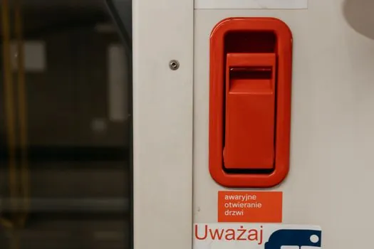
The emergency stop must be self-latching: once struck, it stays in the actuated position until a deliberate reset action is performed at the device itself, and that reset must not restart the machine, it must only re-enable the normal start circuit [S3][S4]. The unlatching direction must be identified on or near the device (typically a twist arrow or a "pull to release" legend), and the contact block must be direct-opening, which in IEC 60947-5-1 terms means the normally closed contact is forced open by a non-spring mechanism when the actuator is pressed, not merely relying on spring return [S3][S4].
Pull-cord variants add one more requirement that the other forms do not: the switch must include cord-breakage monitoring so that a cut or detached cable forces the safety contacts to open just as a deliberate pull would, which is why pull-cord E-stops on conveyors and palletizers carry a 4-wire (or dual-circuit) head rather than a simple 2-wire pull switch [S5]. Wireless and remote E-stop systems exist and are in commercial use, but they have to satisfy the same risk-reduction performance targets as wired devices under ISO 13849-1 and the application-specific ISO standards; for a Category 0 or Category 1 stop function the wireless link has to be designed against the same Performance Level the wired equivalent would meet.
Acceptable vs Disallowed E-Stop Forms: A Comparison
The decision matrix for selecting an E-stop actuator breaks down cleanly against four criteria: visibility, single-action latching, direct-opening contacts, and reset-without-restart. A mushroom-head pushbutton scores high on all four, which is why it is the default on industrial control panels and why it is the canonical example in EN ISO 13850 [S2][S4]. A palm button or palm-operated pushbutton scores equally well on latching and reset, and is preferred where the operator is likely to strike with the heel of the hand rather than a fingertip. A pull-cord switch scores high on accessibility (a worker can trigger it from anywhere along the line) and high on latching, but the cord-breakage monitoring requirement adds wiring and test overhead. Foot-operated switches without a guard are accepted, but the unguarded pedal itself becomes a snag point, so most plants now prefer a guarded foot switch on a hinged cover.
By contrast, flat panel-mount switches and touchscreen E-stops fail the tactile/latching test and are explicitly disallowed by NFPA 79, even though a touch HMI may offer the most flexible placement, because the standard treats E-stop as a hardwired safety function, not a software interlock [S3]. A practical selection rule: if the candidate device cannot be operated by a gloved, panicked hand without looking at it, and cannot be left in the actuated state after the hand is removed, it is not a compliant E-stop no matter how red it is.
Where Color and Shape Apply, and Where They Do Not

The red/yellow rule applies to the emergency stop function specifically, not to every stop on a machine. NFPA 79 deliberately reserves the combination, so a normal "cycle stop" or "feed hold" button must be a different color (typically grey, black, or blue) even though it physically halts the same axis [S4]. OSHA 1910.144 is narrower still: it speaks to the red safety color for fire equipment, danger signs, and emergency stop bars, and leaves ordinary stop buttons to other color conventions [S1][S9]. This is also why a red mushroom without the yellow field, or a yellow mushroom in any configuration, is not a compliant E-stop: the red/yellow pairing is the legal signal, and dropping either element breaks the visual contract that lets a new operator on shift recognize the device in under a second [S3][S4].
A related pitfall in panel retrofits: when a machine is refurbished and a "real" E-stop is added next to an existing red pushbutton used as a non-safety stop, the non-safety button has to be re-colored, because two adjacent red mushrooms, one with yellow and one without, will be read by an operator as the same function. The explosion-proof E-stop variant carries the same red/yellow color rule under ATEX/IECEx, with the additional constraint that the enclosure and the contact block must be rated for the zone; the color does not relax for hazardous areas, only the mechanical and ignition-protection design does.
Typical Specs to Put on a Purchase Order
A specifier-ready description that satisfies all five governing documents reads: "Emergency stop device, twist-to-release or pull-to-release, mushroom-head actuator minimum 40 mm diameter, red actuator on yellow background, mechanical self-latching, direct-opening contacts per IEC 60947-5-1, positive opening force verified, terminal markings per IEC 60947-5-5, legend 'EMERGENCY STOP' or ISO 7010 symbol on yellow field, IP65 minimum front-of-panel, suitable for Category 0 or Category 1 stop per NFPA 79 and ISO 13850 [S3][S4][S8]." For a panel-mounted machine control station, the yellow background is normally delivered as a yellow legend plate, not a repainted enclosure, because that keeps the yellow as a replaceable wear part. For a construction machinery E-stop such as on an excavator or mobile generator, the same rules apply but the actuator is normally a larger 60 mm head for glove operation and the housing is rated to the vehicle vibration and ingress profile.
Compliance audit: the proof points an inspector or end user will check are (1) red actuator, (2) yellow field, (3) mushroom/palm head at least 40 mm, (4) positive-opening NC contact mechanically linked to the push, (5) reset action that does not start the machine, and (6) where the device is color-marked sensor-equivalent, a color-mark sensor on the legend background is not part of the standard; the yellow is for human eyes, not machine vision, so do not specify a "sensor-friendly" yellow thinking it links to a vision system.
Sourcing, Standards, and Failure Modes to Watch

The five standards that matter for color and shape are EN ISO 13850 (principles for design), EN/IEC 60204-1 (electrical equipment of machines), EN/IEC 60947-5-5 (electrical emergency stop devices with mechanical latching function), NFPA 79 (Electrical Standard for Industrial Machinery, US), and OSHA 29 CFR 1910.144 (Safety color code for marking physical hazards) [S1][S2][S3][S4]. The two most common on-site failure modes are (a) the yellow legend plate gets replaced after damage with a generic grey or white label, which silently degrades the device from "compliant E-stop" to "red button," and (b) the contact block gets swapped for a non-positive-opening part during repair, which retains the red/yellow look but loses the direct-opening guarantee that the safety circuit depends on [S4]. A third, less obvious failure is the use of a red illuminated pushbutton (a red LED ring) for the E-stop: a lamp-out condition can make a "red" E-stop look dark, so NFPA 79 and ISO 13850 both treat the mechanical color, not the illumination, as the legal signal.
Trackable signals for the next spec cycle: the 2026 revisions being monitored by safety committees are updates to the ISO 13850 risk-graph language and the harmonization of pull-cord monitoring wording with ISO 13849-1 performance-level tables, neither of which is yet finalized in the public review drafts, so any spec written against the published 2015 edition of ISO 13850 and the 2024 edition of NFPA 79 remains the safe baseline. For a deeper look at how a related safety component, the guard locking switch, handles door-position versus lock-status wiring, the same positive-opening contact principle applies and is worth comparing side-by-side when sizing a control panel.