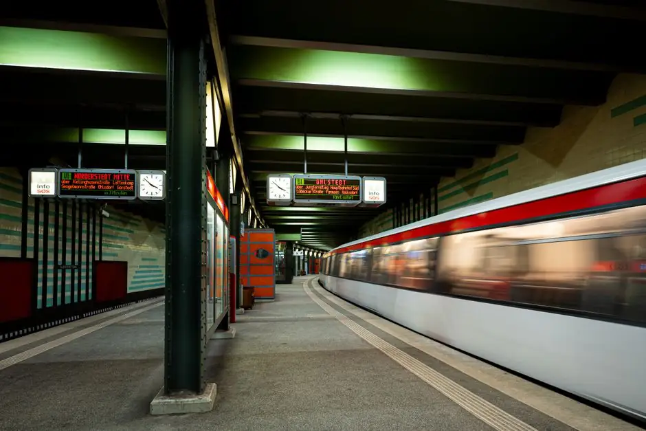
EtherCAT Distributed Clocks lock every slave and the master to a common 32-bit system time, defined in 1 ns units from 1 January 2000, with an effective local clock step size of 10 ns [S1][S4].
For motion sampling this translates into typical jitter well below 1 microsecond, even when the communication cycle itself jitters, and full compliance with the timing model of IEEE 1588 Precision Time Protocol [S4].
Distributed Clock fundamentals and the 10 ns step
The DC mechanism is initialised by the master through a broadcast write that latches each slave's internal timer twice on receive and on loop-back return, after which the master computes per-slave propagation delay, writes the offsets, and forces the first slave to act as reference clock [S4]. Each EtherCAT SubDevice Controller (ESC) then exposes Register 0x910 to carry system time, and the SYNC0 pulse is generated in hardware from that timer [S2].
Continuous re-synchronisation is required to cancel oscillator drift between slaves, so the master re-issues the broadcast at a configurable interval and each slave either trims its local oscillator rate or applies an internal correction [S4]. In practice the local step size is 10 ns, so a SYNC0 event can be scheduled with 10 ns resolution inside a 1 ms cycle, which is what gives the bus its sub-microsecond motion profile [S1].
Master-side sync: DCM modes and trade-offs
On the MainDevice the EC-Master stack synchronises the local cycle timer to the SubDevice acting as reference clock through Distributed Clock MainDevice Synchronization (DCM) [S2]. The cycle is driven by an OS timer interrupt on the master and an independent oscillator on the reference slave, so DCM must initialise, stabilise, and then maintain lock between the two [S2].
Frame handling on the master is split into discrete jobs: Process Inputs to copy latched input data, application calculation, Write Outputs to push new process data via DMA into the Ethernet controller, and EC-Master Administration to run the state machines [S2]. The DC SYNC0 signal must be raised AFTER the cyclic frame has been processed on the SubDevice, otherwise the slave samples stale data and motion axes will not be simultaneous [S2]. Engineers selecting a remote I/O module should verify the vendor documents this ordering explicitly, because some non-DC slices can sit in the same rack without breaking the bus, but they cannot anchor the SYNC0 event.
Oversampling for motion sampling: /16 sub-division in practice
Beckhoff's XFC architecture uses DC time stamping plus oversampling to give extreme timing resolution, with the published spec floor at 10 ns and 1,000 distributed digital I/Os updateable inside a 30 microsecond window [S5]. A representative terminal pair, the EL1262 digital input oversamples the bus cycle at 100 microseconds down to 10 microseconds per sample, while the EL2262 output generates the short pulses downstream [S5].
Field experience from January 2025 confirms the /16 sub-division is real but unforgiving: a WAGO Edge Controller 752-8303/8000-0002 running CODESYS V3.5 SP19 Patch 7, paired with a Beckhoff EKM1101 coupler and two Beckhoff ELM3002_0205 analog input slices, runs a 1.25 ms task with the synch unit at 78.125 microseconds, but configuration errors in DC Cyclic Unit Control can stall the slave in PRE-OP and prevent OP-mode entry [S3]. When the same stack is forced into OP with a faulty DC table, the link latches the last valid sample on a 110 V 60 Hz sine wave until the bus recovers, a classic symptom of SYNC0 firing before the frame is committed [S3]. This is the same mechanism a motion controller relies on for coordinated axis moves, so the failure mode is the canary for the whole machine.
Where DC is required, and where it is optional
DC support is mandatory on any slave that participates in feedback, time-stamped acquisition, or synchronised output, because the SYNC0 pulse is the only way the controller can guarantee a sample-and-hold instant that is identical across the rack [S4]. Slaves that are pure slow I/O do not need DC: valves, basic discrete I/O, and slow temperature sensors can run on the bus cycle alone without breaking determinism, since their latency budget is several orders of magnitude larger than the 10 ns DC step [S7].
On the linear motion axis side, however, omitting DC re-introduces the very clock shift the protocol was designed to remove, and is rarely acceptable for multi-axis registration. The rule of thumb from the integrator community is: if the slave's value is consumed in a closed loop at cycle time, it must support DC; if it is only monitored by a human or a slow trend, it can stay non-DC [S7].
Wiring DC across vendors and PTP time slices

Cross-vendor synchronisation is typically handled by injecting IEEE 1588 PTP into the EtherCAT line via a dedicated slice, for example the Beckhoff EL6688, which then feeds the robot controller's X46 port and aligns the two clocks to the same time base [S6]. In Kollmorgen AKD drive retrofits this pattern is the recommended path to keep KRC4 trajectory interpolation aligned with the EtherCAT bus, and the same EL6688 approach is used to bring third-party PTP grandmasters into the DC domain [S6].
On the I/O side, terminals like the EL1252 timestamp input and EL2252 timestamp output use the DC SYNC0 to give exact reaction time rather than minimum reaction time, which is the distinction between a timestamped event and a fast but skewed event [S5]. For discrete motion, the difference is small (microseconds), but for high-speed registration against a moving web it is the difference between a working reject gate and a scrap rate.
Comparison: DC-capable vs non-DC EtherCAT slaves on motion-relevant criteria
On a motion-sampling axis the four criteria that matter are: synchronisation jitter, SYNC0 resolution, bus-cycle load, and recovery from a frame error. DC-capable slaves reach sub-microsecond jitter and 10 ns SYNC0 resolution because the hardware timer is the reference, while non-DC slaves inherit whatever drift the bus cycle has and can only be sampled at cycle boundaries [S4][S1]. Bus-cycle load for DC slaves is identical to non-DC under nominal conditions, but recovery differs sharply: a DC slave detects a missed SYNC0 and re-arms, whereas the 110 V 60 Hz case in the WAGO thread shows a non-DC path simply latches the last good value and the controller has to detect the freeze [S3]. Cost-wise, DC adds the ESC silicon for the timer register and the Register 0x910 logic, which is why a low-cost slice with no feedback is allowed to omit it [S7].
Limits, failure modes, and selection checklist

Three failure modes dominate the field reports. First, DC Cyclic Unit Control misconfiguration prevents OP-mode entry and the slave hangs in PRE-OP, a configuration error rather than a hardware fault [S3]. Second, sample latching on link interruption, where the input freezes on the last valid value until the bus recovers, which is acceptable for monitoring but unacceptable for closed-loop control [S3]. Third, oscillator drift between two DC slaves if the re-synchronisation broadcast interval is set too long, which is fixed by tightening the interval or moving to a hardware-shared PTP source [S4][S6].
For a motion-sampling spec, the checklist is: (a) the slave must expose DC support and the SYNC0 event must be scheduled after the cyclic frame on the slave, (b) the master must run DCM in a mode that maintains lock, not just initialises it, (c) any non-DC slice in the same segment must be limited to slow feedback so its drift cannot contaminate the loop, and (d) for cross-vendor integration, a PTP time sync slice is the cleanest way to keep the robot and the bus on the same time base [S1][S2][S6][S7]. Engineers wiring EMR versus SSR switching blocks for low-speed field devices, like those covered in the EMR vs SSR decision map, can park those non-DC loads on a separate segment so the motion segment stays pure DC.
Trackable signals for the next review: the CODESYS/WAGO DC oversampling thread (last activity March 2025) for any patched firmware that resolves the 78.125 microseconds sub-division stall, and any new XFC-class oversampling terminal that pushes the sub-cycle ratio beyond /16 [S3][S5].