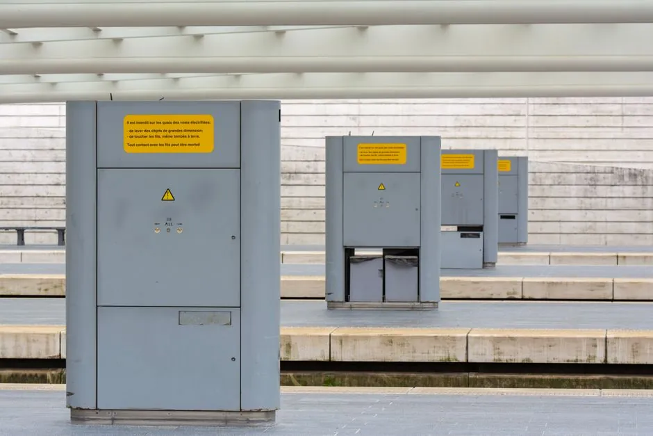
Most factory-built ATEX/IECEx explosion-proof junction boxes ship with 4 to 8 pre-machined cable entries, threaded G-3/4, M20/M25/M32, or 1/2 in to 1.5 in NPT, and SharpEagle's CNEx19.2768X-rated 304 stainless steel unit is a representative 4 in / 4 out configuration on a 400 mm x 500 mm x 150 mm body [S1].
Entry count is not a free variable: it is fixed by the Ex certificate scope, and any field-drilled hole outside that scope invalidates the protection concept, which is the single most common spec error on EPC projects [S3].
Why Entry Count and Box Size Are Coupled, Not Independent
An explosion-proof enclosure carries one rating for the assembly as built; the certificate lists the maximum entry count, thread types, and approved gland families, so adding an extra conduit entry on site voids the marking [S3]. Selection flow therefore starts with cable quantity, conductor cross-section, terminal count, and gland size, all of which fix the minimum internal volume before material is even discussed [S3][S5].
Larger enclosures physically support more entries and more wiring room, which is the second-order reason oversizing is common: a 400 mm x 500 mm x 150 mm box can accept 4 G-3/4 entries per face, while a 200 mm x 200 mm x 150 mm unit is usually limited to 2 to 3 [S1][S2]. SharpEagle's published spec also bakes the operating envelope into the same build: ambient -30 deg C to +70 deg C, 80 to 106 kPa atmospheric pressure, and IP68 [S1].
Thread Standards: G, NPT, and Metric Are Not Interchangeable
Three thread families dominate hazardous-location junction box entries, and mixing them is a frequent procurement error: G-3/4 (BSP parallel, common on ATEX/IECEx kit from Asia and the Middle East), NPT 1/2 in / 3/4 in / 1 in / 1.5 in (tapered, dominant in U.S. Division/NEC projects), and metric M20 / M25 / M32 (parallel, standard on most European IECEx hardware) [S5].
Gland choice must match both thread and certificate: a G-3/4 entry paired with an NPT gland will not seal to IP66/IP68, and the Ex d flamepath length changes with thread form. For reference, the SharpEagle datasheet lists only G-3/4, so specifying NPT glands on that exact SKU would fail [S1]. When a project is genuinely multi-region, dual-certified boxes (ATEX + IECEx + cULus Class I Div 1) are now standard and remove the threading argument entirely [S2].
Sizing Rules: NEC 314.28 for Wiring, Not the Ex Rating
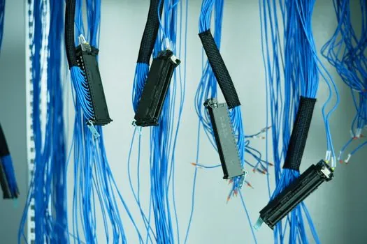
Wire bending space inside the box is governed by NEC 314.28(A) for conductors 4 AWG and larger, applying separate straight-pull, angle-pull, and U-pull calculations that depend on the largest raceway entering the box [S4]. A 2 in raceway carrying 1/0 AWG conductors needs far more box length than intuition suggests, which is why pull/junction box sizing tables, not eyeballed dimensions, drive compliant U.S. installs [S4].
For smaller conductors below 4 AWG, 314.16 boxes the standard cubic-inch capacity per conductor, and typical single-gang boxes sit at roughly 2 in x 3 in x 3.5 in while 4 in x 4 in square junction boxes remain the workhorse for branch-circuit splicing [S7]. The critical point is that NEC sizing and Ex sizing layer on top of each other: a box can satisfy 314.28(A) and still fail the Ex certificate if its internal volume per entry is too low for the chosen gland family [S3][S4].
Enclosure Material Choices and Their Trade-offs
Three material families cover almost every spec: aluminium (light, cost-effective, common on offshore modules), 304/316 stainless steel (corrosion-resistant, heavier, mandatory for sour service NACE MR0175 environments or coastal CIP), and GRP / glass-reinforced polyester (non-conductive, used where galvanic isolation or RF transparency matters) [S3]. The SharpEagle 304 SS unit is rated Ex d IIB T6 Gb / Ex tD A21 IP68, T80 deg C, which is the typical mid-tier gas-group IIB marking for hydrocarbon and ethylene atmospheres [S1].
Material and entry count trade against each other: aluminium walls are easier to machine for custom entries but limit wall thickness for Ex d flamepath, while stainless accepts fewer entries per face before structural stiffness drops. For hydrogen or acetylene service (gas group IIC), entry spacing and wall thickness both tighten, often forcing a step up in enclosure size even when terminal count is modest.
Entry Layout: Terminals Inside, Glands Outside, Both Counted
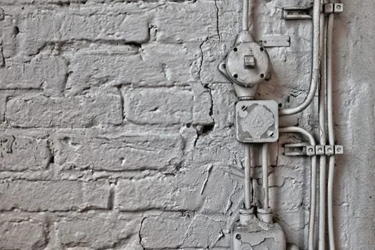
Engineers routinely conflate entries with circuits; they are not the same. A 4 in / 4 out box such as the SharpEagle unit can carry dozens of internal terminal blocks because each entry may host a multi-core armoured cable with several conductors, and the Ex certificate is written around the entry geometry, not the conductor count [S1][S3]. Specifying terminal count separately from entry count is therefore the correct flow.
Gland selection sits at the same boundary: armoured cable glands (e.g. Hawke A type) need more internal box length than unarmoured compression glands, and the certificate will list the approved gland series by part number, not by generic type. Substituting a non-listed gland is the second most common spec error after field-drilling a new entry, and both actions void the marking [S3].
When a Standard Box Fits and When It Does Not
Standard off-the-shelf 4 in / 4 out or 8-out ATEX boxes cover roughly 80 percent of skid-package I/O on chemical and pharma projects, the exact pattern SharpEagle's 400 mm x 500 mm x 150 mm format targets [S1]. They fail when the project needs more than 8 entries, IIC gas group certification, ambient outside -30 deg C to +70 deg C, or ambient pressure outside 80 to 106 kPa, and at that point the box becomes engineered-to-order with a new certificate path [S1][S2].
For a deeper look at how Zone 1 and Zone 2 map to specific protection concepts and category numbers behind these Ex d IIB markings, see the Zone 1 vs Zone 2 Ex electrical spec comparison. Buyers should also confirm that the selected gland family and entry count are written into the supplier's IECEx/ATEX certificate annex, not just the marketing datasheet, before releasing a PO.