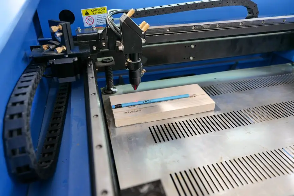
A fiber laser marker writes DataMatrix, GS1, and UDI codes directly onto steel, aluminum, titanium, brass, and coated metal material at cycle times as short as 0.6 sec per part, against stamping-press throughputs that routinely exceed 60 parts/min [S5]. The codes survive downstream e-coating, stamping, and abrasion because the mark is formed by vaporization, oxidation, or melt-resolidification of the substrate itself, not by an ink or label [S1][S5].
Direct part marking (DPM) by laser has become the default traceability node for tier-1 automotive, aerospace, and medical-device suppliers, replacing batch numbers with unique identifiers that tie each physical component to its production data, lot, facility, and inspection record [S5][S6][S8]. Unlike pin stamping, laser marking is non-contact, so it does not impose mechanical stress on the part and does not slow the press while identifiers are updated in milliseconds through a PLC link [S2][S5].
Marking modes: annealing, etching, engraving
Fiber-laser systems offer three workhorse processes, and the choice is driven by substrate, finish, and downstream exposure rather than by throughput alone. Engraving or ablation vaporizes surface metal to produce a deep mark that resists heavy abrasion, which is the default for metal material that will see tool contact or grit blast [S2]. Annealing heats the metal below the surface to grow a controlled oxide layer, producing a dark, high-contrast mark with no material removed, which is why it is the preferred mode for austenitic stainless steel, titanium, and finished medical or aerospace surfaces where corrosion resistance and surface finish must be preserved [S2][S6]. Etching melts and rapidly re-solidifies a thin skin, leaving a slightly raised textured mark and is typically selected for high-speed alphanumeric or logo work where cycle time dominates [S2].
For highly reflective substrates such as polished aluminum or copper, fiber sources are consistently recommended over CO2 or green lasers because the 1.06–1.07 µm wavelength couples into the metal more efficiently, producing a clean mark without thermal drift across the field [S2][S6]. All three modes are dry, consumable-free processes, which removes the recurring cost and chemical handling associated with chemical etching and inkjet [S2][S7].
Cycle time, code grade, and machine-vision feedback
Production-line laser marking on stamped or machined metal is sized to the press, not the laser: a press running above 60 parts/min requires the marking system to identify each part in under 1 sec, and current galvo-based fiber systems deliver DataMatrix marks in approximately 0.6 sec per part, well inside that window [S5]. The system reads its traceability string (part number, serial, lot, production timestamp, facility, source) from the press PLC or PC and updates the marking parameters in a few milliseconds between parts, with no operator intervention [S5].
Closed-loop verification is now standard on industrial cells: the laser marks the code, an integrated 2D vision reader grades it against ISO/IEC 15415 or AIM-DPM quality thresholds, and the result is written back to the MES so a low-grade mark triggers a rework flag rather than a silent reject [S3][S4]. A typical spec floor for automotive DPM is grade C or better at the press exit, with re-verification after e-coat or shot-blast because downstream processes can deform or obscure the symbol [S3][S5]. The same architecture underpins GS1 and Unique Device Identification (UDI) compliance, where the marked string must remain machine-readable for the full service life of the part [S1][S3].
Where the mark is applied on the part
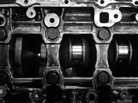
Marking location matters as much as mark mode. On a stamping cell, the most reliable position is on the coil or blank before it enters the press, which sidesteps the geometric access problem of marking finished, drawn, or trimmed parts at the press exit [S5]. Forged, cast, or machined components are normally marked on a machined reference face, a flange, or the OD of a cylindrical feature where the galvo head can keep the mark in the focal plane and the code can be inspected by a fixed camera [S2][S5].
Surface condition drives both laser choice and parameter set. Oily coil and blank surfaces are common in stamping, and IP-rated optics and enclosures (typically IP54 or higher on the marking head) are required because oil mist and dust will degrade unprotected lenses and galvo mirrors within days on a high-volume line [S5]. Coated metals, anodized aluminum, and plated parts can be marked through the coating or by controlled ablation of it, but the underlying substrate composition still dictates contrast and long-term legibility, so the laser setup has to be qualified per coating chemistry rather than per part number [S2][S6].
Selection criteria: fiber vs CO2 vs Nd:YAG vs green
The dominant decision for a new metal-traceability cell is the source wavelength, and for steel, stainless, titanium, aluminum, brass, and coated metals the fiber laser at around 1.06 µm is the default because absorption, beam quality, and electrical efficiency all favor it over flash-lamp-pumped Nd:YAG and CO2 [S6][S7]. Nd:YAG (1.064 µm) remains in service on legacy lines and still marks metals well, but its wall-plug efficiency, maintenance interval, and beam mode stability are inferior to modern fiber, and most retrofits are triggered by running-cost reduction rather than mark quality [S7].
Green (532 nm) and UV (355 nm) sources are reserved for specialty tasks: highly reflective nonferrous metals, certain semiconductor and medical alloys, and the small subset of plastics or coated glass that absorb poorly at 1 µm [S2]. A practical selection rule is to use fiber for steel, stainless, titanium, and aluminum; use green only when a fiber trial fails to produce contrast on a specific reflective alloy; and treat UV as a last-resort or plastics option, not a default. Average power for DPM on metal typically lands in the 20–50 W fiber range, with MOPA configurations favored where pulse duration must be tuned to suppress heat affect on thin or polished parts [S6][S7].
Standards, durability, and who it is for
Laser marking does not replace a quality system; it is the data-carrier layer beneath one. The mark itself is governed by symbol-quality standards (ISO/IEC 15415 for 2D codes, ISO/IEC 16022 for DataMatrix), by application-specific rules such as GS1 for automotive and aerospace logistics, and by UDI for medical devices, while the data behind the code is managed inside the manufacturer's MES, with retention windows set by sector regulation rather than by the laser [S1][S3]. In oil and gas, NACE MR0175 environments and subsea components, the relevant question is not whether the laser can mark the alloy but whether the mark is placed in a recess or on a low-stress face so that corrosion and fatigue behaviour are not affected by the marking process [S2].
Laser DPM is the right answer for high-volume metal components that need a permanent, machine-readable identifier tied to a digital record, for example automotive stampings, aerospace fasteners and blades, surgical instruments, and serialized fittings. It is the wrong answer for very short runs of large structures where fixturing cost dominates, for components that must remain absolutely stress-free at a critical surface (where an alternative low-stress identification method or a recess should be specified), and for any marking requirement that can be satisfied by a paper or polymeric label that will not see abrasion, chemicals, or UV [S2][S3][S5]. Compared with pin stamping, laser marking is faster to change over, cannot wear a character, and produces a code rather than a batch number; compared with chemical etching, it eliminates acid handling, ventilation, and waste treatment; compared with inkjet, the mark cannot be solvent-washed off and does not introduce a consumable [S2][S4][S7].
Failure modes and shop-floor pitfalls
Three failure modes account for most line-side rejects. First, contrast loss on stainless after passivation or after e-coat bake, which is solved by tuning annealing parameters rather than increasing power, because excess power simply roughens the surface without raising the grade [S2][S5]. Second, code deformation after stamping or shot-peening downstream of the laser, which is solved by moving the mark upstream onto the blank or by switching to a deeper engraved mode, and by re-grading the symbol after the downstream process rather than at the press [S3][S5]. Third, lens contamination from oil mist and coolant on stamping cells, which is solved by specifying IP-rated enclosures, local extraction, and a scheduled optics-cleaning interval rather than by relocating the laser head [S5].
For shop-floor integration, the Industrial vs Commercial Ethernet Switch per-port price gap is worth weighing alongside the laser because the MES link from a marking cell is typically carried over industrial Ethernet, and the PLC handshake, vision grading, and reject signal all ride on the same switch. On high-mix cells, the same marking software platform should drive both the laser and the verification camera so that a recipe change automatically updates the grading thresholds; this is where the practical difference between a marker and a traceability station shows up on the OEE dashboard [S3][S4].
Trackable signals for the next planning window: suppliers are increasingly quoting cycle times below 0.5 sec per DataMatrix on 30–50 W MOPA fiber heads, AI-assisted grading is being integrated into the same controller as the galvo, and the GS1 and UDI application profiles continue to absorb new data fields that the DPM symbol has to carry without growing the physical mark beyond the available face width [S1][S5][S8].
Component reference pages worth checking: metal powder.