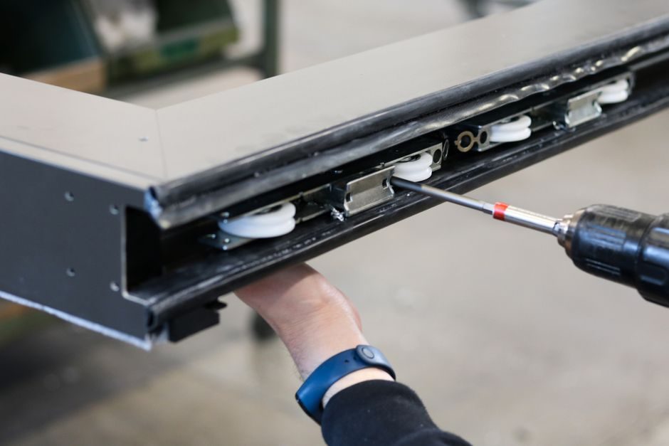
A correctly installed flat belt on a troughed or slider-bed conveyor is a function of three mechanical facts: pulley parallelism held inside roughly 0.5° per meter of center distance, a static take-up tension that keeps the belt carcass above the rated working load, and pulley lagging that lifts the effective friction coefficient above the dry-rubber-on-steel baseline of about 0.20 to 0.25 [S3].
The DJE-series troughed flat-belt conveyor manual from Anhui Deji Huijin (2026-07) sequences the field work into pulley alignment, belt splice preparation, take-up setting, and an empty-load tracking check before any material is fed onto the belt [S3]. The numbers below are the acceptance criteria that manual and comparable OEM service guides publish; specific test values follow each step.
Pulley parallelism and shaft alignment
Head, tail, and snub pulleys must share a common plane within 0.5 mm per meter of center distance; cumulative angular error across the full belt length is held below 0.5° before the belt is pulled on, per the Anhui Deji Huijin DJE flat-belt conveyor manual [S3]. A laser line or dial gauge across both end faces of each pulley is the field test; a feeler gauge on a stretched string between pulley edges is the practical fallback. If the tail pulley is the highest and the belt tracks toward the tail, the head is the typical reference for vertical lift, and the snub or take-up pulley is the steering correction. Skewing a snub pulley by 0.5° to 1° opposite the tracking direction is the standard field correction when a flat belt walks off-center, and the corrected pulley must be locked with both key and locking collar so vibration does not back the adjustment out.
When the head-to-tail span exceeds 8 m, the OEM recommends a 5 m spacing between crown pulleys or crowned idlers, since crowned pulleys alone will not centralize a belt that has wandered because of misaligned shafts. Where crowned pulleys are used, the crown height is generally 8 mm to 12 mm for a 400 mm to 600 mm wide belt; a flat-faced pulley running a flat belt is acceptable only when the conveyor length is short and the take-up stroke is rigid.
Belt selection and width-to-pulley diameter match
Belt width should equal the widest pulley face minus 10 mm to 25 mm of side clearance, and the minimum pulley diameter is set by the carcass plies and the top cover thickness rather than by belt width alone. The DJE OEM manual specifies the pulley diameter table as a function of belt plies and cover gauge rather than as a function of belt width, so a 4-ply belt with a 3 mm top cover is matched to a smaller drive pulley than a 4-ply belt with a 6 mm cover running at the same line speed [S3].
For a frame of reference, common 2-ply PVC flat belts with 1 mm to 2 mm covers are paired with 80 mm to 120 mm drive pulleys on small packaging conveyors, while 3-ply to 4-ply rubber-covered belts with 4 mm to 6 mm covers are paired with 200 mm to 400 mm drive pulleys on aggregate and mining conveyors. A flat belt on a pulley that is too small develops cover cracking and ply separation at the nip within weeks; a flat belt on a pulley that is oversized wastes shaft space and reduces the wrap angle available for friction drive.
Splice geometry and mechanical lacing
For an installation that must be done with hand tools and no vulcanizer, mechanical plate lacing with a hinged fastener is the default. The DJE flat-belt conveyor manual specifies fastener spacing and hinge-pin selection as a function of belt width and rated working load, and the manual calls for the lacing to be countersunk below the belt surface by 1 mm to 2 mm so the fasteners do not score the drive pulley face [S3].
Endless (vulcanized) splicing produces a joint with roughly 90% of the parent belt's tensile strength, while a properly installed mechanical plate lace typically retains 70% to 80%; an installer who needs 100% joint efficiency must specify endless vulcanized splicing, schedule the cure cycle into the downtime, and provide a temperature-controlled splice station on site. Skiving the belt ends to a 30° to 45° scarf before lacing reduces the step at the joint; a square-end lacing without skive produces a bump that the idlers will repeat every revolution and that drives material off the belt at the splice.
Take-up tension and elongation window
Static take-up tension must be high enough that the belt does not slip on the drive pulley under peak load, but low enough that the carcass does not run above 1% to 1.5% elongation during operation. The DJE OEM manual sets the take-up stroke at roughly 1% of the center distance for screw-type take-ups, and at 2% to 3% of the center distance for gravity take-ups on troughed conveyors [S3].
Field test: with the take-up locked, measure the belt span between two idlers, mark a reference span, apply a 1% stretch reference on the belt cover, then back the take-up off until the mark returns. The empty-belt sag between the carrying idlers should be 1.5% to 2.5% of the idler spacing; a sag of less than 1% means the belt is over-tensioned and the bearings will fail, a sag of more than 3% means the belt is under-tensioned and will slip at the drive. On a related note, a properly aligned and tensioned flat belt is the same baseline you want when sizing a belt tensioner, because the tensioner is only correcting for the residual stretch the take-up cannot absorb.
Pulley lagging and friction coefficient

Pulley lagging is the surface treatment that lifts the friction coefficient from the dry rubber-on-steel value of 0.20 to 0.25 into the 0.35 to 0.55 range, and that additional friction is what lets a flat drive transmit the rated load without a tensioner take-up that would over-stress the belt.
Field test for lagging quality: with the belt running empty at full speed, measure the slip with a strobe on a mark painted on the pulley face; slip should be below 0.5% at steady state, and any reading above 1% means the lagging is glazed and either needs to be re-grooved or replaced. Lagging that has been diamond-grooved in a herringbone pattern holds debris in the grooves and maintains friction coefficient in dirty service; a smooth lagging will polish under fines and revert to the steel baseline within weeks.
Tracking check and empty-load commissioning
Before any product is fed onto the belt, run it empty for at least 15 minutes at full speed and observe the tracking at the head, tail, and at least one intermediate idler. The DJE commissioning procedure specifies that the belt should track inside the pulley centerline within 5 mm to 10 mm at steady state, and that any wandering beyond 15 mm requires a re-skew of the steering pulley before the conveyor is released to production [S3].
If the belt tracks to one side at the head and the opposite at the tail, the head and tail pulleys are not parallel; if it tracks to the same side at both ends, the take-up is binding on one side. A belt that oscillates back and forth under no load is almost always a tension problem, not an alignment problem; raise the take-up 2% to 3% and re-check. A flat belt is a chain of mechanical errors in series, so the installer who measures pulley parallelism, sets the take-up to the elongation window, and verifies the lagging friction coefficient has cleared the three failure modes that bring a flat belt down inside the first shift. To extend the same commissioning discipline to a ribbed profile, see the spec map for ribbed belt selection and to understand how the same belt family runs on flat idlers in conveying service, see the belt conveyor reference.
For related coverage, see Silicon Wafer Industry 4.0 Adoption: Specs, Standards, and Fab Floor Reality in 2026.