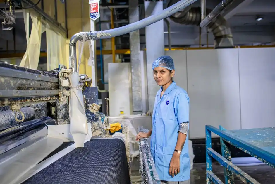
A hydrokinetic fluid coupling, with a pump impeller on the input shaft and a runner on the output shaft sharing a sealed oil-filled casing, transmits torque through the working fluid rather than metal-to-metal contact, delivering inherent soft-start and overload protection [S6][S7]. On textile lines running carding, ring spinning, weaving, and stenter/dryer equipment 24/7, that slip-based torque ramp is the primary reason the technology is specified over rigid or elastomeric couplings [S3].
Textile mill duty differs from cement or mining: dust ingress and ruggedness are secondary to vibration control, smooth torque delivery at start, and long mean-time-between-failure under continuous duty at ambient 30-50 deg C [S2]. Selecting a fluid coupling for a textile drive therefore starts with service factor against the driven machine class, not just rated power.
Why a Fluid Coupling, Not a Rigid or Gear Coupling, on Textile Lines
A fluid coupling's transmitted torque rises with the square of input speed, so a motor started direct-on-line produces a gradual torque ramp instead of an instantaneous step, which limits the starting shock seen by the gearbox and belt drive [S6]. For a carding machine or ring-frame drive this directly translates into fewer broken belts, less yarn wastage at start, and longer motor winding life [S2][S3]. Compared to a torsionally rigid gear coupling, a fluid coupling accepts substantial angular displacement and absorbs torsional vibration through internal slip, so the connected gearbox sees far lower peak torque during acceleration and load transients [S5]. Compared to a flexible elastomeric jaw coupling, the fluid unit handles higher continuous slip losses without the spider element overheating, and is the preferred path when the driven machine's inertia ratio Wk2 (driven) / Wk2 (motor) exceeds roughly 3:1 and the start under load is frequent [S2]. On the flip side, a fluid coupling cannot transmit torque at zero slip when the application needs precise synchronisation, e.g. positive registration between adjacent print rollers or position-controlled rapier drives, so those are better served by a rigid or disc coupling instead.
Service Factor and Load Classification for Textile Machines
Selection begins by classifying the driven machine and applying the manufacturer's service factor (SF) to the nameplate power. For textile duty the typical service-factor bands the buyer's guide recommends are: carding machines and ring spinning frames at SF 1.4-1.6, weaving looms (rapier, air-jet, projectile) at SF 1.6-1.8, and stenter/dryer fan or blower duty at SF 1.2-1.3, against a 16-24 h/day continuous operating envelope [S2]. Shock-loaded drives, e.g. opening/cleaning lines and bale pluckers, fall in the 1.8-2.0 band because the start is essentially under peak load [S2].
Match the catalogue rating to the factored load (P_motor x SF), and confirm the coupling's slip at rated load stays in the 2-5% band; above 5% the unit is undersized and will run hot, below 2% it is over-rated and you have lost the soft-start benefit [S2]. In practice, for a 30 kW carding motor on a 1.5 SF duty, target a coupling rated for at least 45 kW continuous, with a peak torque capacity two to three times rated so a jammed lap or wet lap event does not shear the shaft or burst the seal [S2][S5].
Fill Ratio, Thermal Rating, and Working Fluid
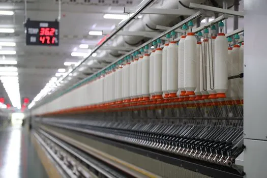
Fluid couplings are torque-controlled by fill level, not by the impeller geometry. A partial fill gives a soft, low-torque start with high slip; an overfill drives the unit close to 1:1 lockup and removes the cushioning the textile line was paying for [S6]. Most OEM catalogues, including the Flender FLUDEX line documented in FLE 10.4, list a fill-volume table per coupling size in litres, with a +/- 10% tolerance band on the recommended fill [S5].
Working fluid is typically mineral hydraulic oil ISO VG 32 or VG 46 for ambient 20-50 deg C textile halls, with synthetic fluids specified where ambient exceeds 60 deg C, e.g. in stenter dryer rooms or where steam leakage raises floor temperature [S5]. Thermal capacity is the second hard limit: a fluid coupling dissipates slip losses as heat, and the catalogue will quote a maximum permissible slip power (kW of heat to reject) per coupling size. Exceed it and the seals fail inside 6-12 months [S2]. For a 24-hour continuous shift, derate the catalogue thermal rating by 10-15% to keep bearing and seal life on plan.
Comparison: Fluid, Mechanical, and Hydraulic Couplings on Textile Duty
Side-by-side, the three coupling families the textile trade uses behave very differently. The table is built from the selection criteria the buyer is actually weighing at the desk [S3].
Start behaviour: fluid couplings give a 3-10 second torque ramp proportional to slip, mechanical couplings transmit full motor torque at the first half-cycle, and hydraulic couplings use an external control circuit to shape the start curve [S3]. Overload protection: fluid units slip rather than fail, mechanical units need a shear pin or slip-clutch add-on, hydraulic units have adjustable relief [S3]. Vibration damping: fluid and hydraulic both good, mechanical is poor at high speed. Maintenance: mechanical lowest (no seals, no fluid), fluid moderate (oil change every 8 000-12 000 h, seal inspection yearly), hydraulic highest (filter, valve, cooler) [S2][S3]. Cost: mechanical lowest, fluid mid, hydraulic highest. For carding, ring spinning, weaving, and stenter drives the soft-start + slip protection combination of the fluid coupling wins, while for high-speed winding, precision take-up, and inter-roller drives the rigid or disc coupling wins on positional accuracy [S3]. Where drives are interlocked with a shaft coupling requirement for misalignment compensation plus a fluid start, designers sometimes stage a fluid coupling at the motor and a flexible coupling downstream, but the textile practice is increasingly to combine both functions in one fluid unit with elastomer element to keep the BOM short.
Mounting, Cooling, and Maintenance Footprint in a Mill
Most fluid couplings mount between the motor shaft and the gearbox input flange (or pulley) on a common baseplate; the impeller half bolts to the motor, the runner half to the driven side, and the housing is filled via a plug on the casing [S5][S7]. For textile halls, two practical rules apply. First, leave a 150-200 mm radial clearance for seal removal and a sight glass or dipstick access; second, mount the coupling in a horizontal orientation if the design allows, because vertical mounts reduce bearing life and trap air pockets that spike temperature during start.
Cooling is passive in 90% of textile applications, but for stenter fans and large card drives above 75 kW, an externally-finned housing or a small fan cowl cuts bearing temperature by 10-15 deg C, which is meaningful in a hot, humid stenter room [S2][S5]. Maintenance-wise, the realistic interval to write into the mill's PM plan is a 4 000 h visual check (oil colour, leak at seal, unusual noise), an 8 000-12 000 h oil change with the OEM grade, and a 24 000 h bearing and seal replacement, with the seal replaced immediately if oil appears at the shaft exit [S2].
Limits, Failure Modes, and When Not to Use a Fluid Coupling
The classic failure modes on textile lines are thermal overload from chronic overfill or undersizing, seal failure from particulate ingress, and bearing failure from vibration amplified by a soft mount [S2]. Operators see the first warning as rising oil temperature at the housing (typically a hand-readable 70-80 deg C versus a healthy 50-60 deg C) and the second as visible oil weep on the shaft. A common mis-spec is using a fluid coupling where a jaw coupling would do, which raises cost and adds a maintenance item with no benefit on a low-inertia drive.
Do not specify a fluid coupling where the process needs 1:1 speed synchronisation (e.g. print roller registration, draw-frame creel sync, certain stenter chain drives), where ambient is below -10 deg C (oil viscosity spikes and the unit will not transmit rated torque on cold start), or in a cleanroom-style synthetic yarn hall where oil mist from the seal is unacceptable [S2][S3]. For ATEX-classified zones, confirm the coupling has a documented non-sparking rating from the manufacturer; standard fluid couplings are not ATEX-certified by default and the mill will need a tagged variant [S2].
Procurement Checklist and Trackable Signals

Use the spec map the catalogues give you: rated power (kW), peak torque (Nm), service factor applied, fill volume in litres, working fluid grade, slip at rated load, thermal rating (kW of slip loss), and a written MTBF target from the vendor [S2][S5]. The cleanest next step is to request a thermal-duty calculation from the supplier, with motor nameplate, driven machine Wk2, starts per hour, and ambient temperature as inputs; a vendor who will not do this calculation is one to de-list.
Trackable signals to watch: Flender's FLUDEX line moved to FLE 10.4 Edition 2026.1 in the current catalogue cycle, and comparable Indian and European vendors refreshed textile-duty technical guides in late 2025 [S3][S5]. For deeper context on how a fluid coupling sits in the broader textile drive train, see the spec map for shaft collar selection in steel mills and the gear coupling selection for cement plant drives note for the high-inertia comparison case. Another nearby industrial spec map worth reading in parallel is the Y-strainer pros, cons, and selection map when sizing upstream hydraulic circuits that feed the same line.