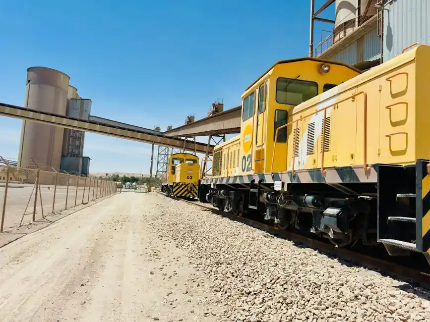
Cement plant drivetrains concentrate the most punishing combination of shock load, dust ingress, and thermal growth in any heavy industry, which is why gear couplings, not elastomeric or chain couplings, dominate kiln, ball mill, vertical roller mill, bucket elevator, and crusher drives [S2][S3].
A gear coupling is a flexible mechanical coupling that transmits torque through meshing crowned external and internal gear teeth, accommodating angular, radial, and axial misalignment while keeping full tooth-face contact; a correctly specified unit, hardened, lubricated, and sealed, delivers multi-decade service in these severe conditions [S2][S3].
Where Gear Couplings Sit in a Cement Plant
The five cement-plant drive classes that consistently demand gear couplings are kiln drives, ball mills, vertical roller mills, bucket elevators, and crushers, and the catalog of couplings tagged "for the cement industry" maps directly onto these five loads [S1][S2]. DirectIndustry lists 14 products across 6 manufacturers (RINGSPANN, DST, jbj Techniques, M.A.T. Malmedie, SGF, ZERO-MAX) flagged specifically for the cement industry, of which 12 are torsionally-rigid flexible and 8 are classified as flexible, with shaft-hub the most common construction at 12 listings [S1].
Industrial gearboxes are the backbone of machines used across cement plants, and the gearbox output shaft to the driven pinion is where the coupling is asked to absorb both steady-state torque transients from the mill and the slow axial growth of a rotating kiln; selecting on catalog number alone, the pattern behind a Southeast Asian kiln-drive failure where tooth wear and elevated vibration showed up three months after a like-for-like swap, is a documented failure mode [S3][S4].
The Five Inputs That Actually Drive Sizing
Gear coupling selection for heavy machinery resolves to five binding inputs: torque capacity, speed, shaft misalignment, environment, and service factor, with installation length and supplier capability as secondary gates [S3][S5]. The torque calculation starts from nominal torque using the standard motor formula: Nominal torque (N·m) = 9,548 × Power (kW) / Speed (RPM), and a 400 kW motor at 600 RPM therefore produces about 6,365 N·m of nominal torque, which must then be inflated by a service factor typically between 1.5 and 3.0 to account for starts, reversals, and shock loads [S3].
With a service factor of 2.0 the same 400 kW / 600 RPM motor demands a coupling rating of at least 12,730 N·m, and AGMA-aligned service factors plus manufacturer catalog data are the published sources for choosing where in that 1.5 to 3.0 band a specific drive sits [S3]. Peak torque from starting, emergency braking, or load surges must be checked against the coupling's maximum rating, and the failure pattern is well known: under-sized couplings exhibit tooth fatigue, accelerated wear, and unplanned downtime within months, not years [S3].
Misalignment, Thermal Growth, and Contamination
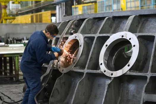
Crowned gear teeth on the hubs let a gear coupling absorb angular, axial, and radial misalignment while keeping tooth-face contact, and AGMA-aligned installation limits plus the manufacturer-specified envelope define the operating window; exceeding those limits is the second-most-common cause of premature wear after under-sizing [S2][S3][S5]. In a cement plant the axial component is not optional: a rotating kiln grows several millimetres along its axis as it heats to process temperature, and the coupling sitting between the kiln pinion and the gearbox output must absorb that growth without shoving the gearbox out of alignment [S3].
Environment is the third input that separates a paper-spec coupling from a cement-spec one: dust, cement fines, and water carry-over from wet-process kilns all attack the lubricant film on the gear teeth, which is why sealed lubricant systems are flagged as a make-or-break feature in kiln-drive retrofits [S3]. The catalog of couplings tagged "high-performance" (11 products), "maintenance-free" (9), and "high load capacity" (8) reflects exactly this dust-and-shock envelope, and "non-lubricated" appears in 8 listings for the lower-torque auxiliary drives where grease-packed gear teeth would be impractical to service [S1][S5].
Construction Choices: Continuous Sleeve vs. Flanged Sleeve
Two constructions cover the vast majority of cement-plant gear couplings, and the choice between them is a torque-and-maintenance trade rather than a performance one [S5]. A continuous-sleeve gear coupling uses a single sleeve covering both hubs, is compact and simple to assemble, and fits small- to medium-duty applications such as bucket elevators and small conveyor drives where ease of field assembly matters more than torque density [S5].
A flanged-sleeve gear coupling uses two flanged hubs bolted together through a centre plate, gives higher torque capacity per envelope, and is preferred on kiln drives, ball mills, and vertical roller mills because the flanged joint is easy to disassemble for inspection without moving either shaft, a critical point when a coupling sits inside a guarded mill drive [S3][S5]. The DirectIndustry construction flags confirm this split: "shaft-hub" leads at 12 listings, "compact" at 7, "flywheel" at 5, and both "with spacer" and "3-part" appear for the longer kiln-drive spans where the gearbox sits back from the pinion [S1].
Comparison: Gear Coupling vs. Alternatives on Cement-Plant Drives

On the four decision criteria that matter most in cement plants, gear couplings sit in a defined position relative to elastomeric, chain, and rigid couplings. Torque density: gear couplings are very high torque density per envelope, elastomeric couplings are medium, chain couplings are high but with axial-pull penalty, rigid couplings are the highest but zero misalignment [S2][S3]. Misalignment: gear couplings accommodate angular, axial, and radial misalignment through crowned teeth, elastomeric couplings accommodate similar but with lower torque, chain couplings are mainly angular, rigid couplings are zero [S2][S5].
Contamination tolerance: gear couplings are good when sealed and lubricated, but vulnerable when seals fail; elastomeric couplings are excellent because the element absorbs particles; chain couplings are poor in dusty cement environments; rigid couplings are unaffected by contamination but transfer every shock [S2][S5]. Service life: gear couplings are multi-decade with proper lubrication, elastomeric couplings are element-limited (typically 3 to 8 years), chain couplings are wear-limited and need tensioning, rigid couplings are the longest but push alignment stress downstream into the bearings [S2][S3]. For kiln, ball-mill, and VRM drives the combination of high torque density, misalignment absorption, and proven service life is why gear couplings win, and for the lower-torque, dust-saturated auxiliary drives elastomeric couplings are often the better fit [S2].
Replacement Indicators and Common Failure Modes
Many gear couplings remain in service for decades, but the wear indicators are consistent enough to be turned into a maintenance checklist: excessive backlash, worn gear teeth, oil leakage, cracked sleeves, hub damage, excessive vibration, lubrication contamination, and repeated seal failures [S2]. Each of these is a stop-watch item rather than a "monitor and plan" item, because the failure of a coupling in a kiln drive or ball mill typically cascades into a multi-day unplanned outage.
The preventive maintenance pattern that follows from those indicators is well documented: keep the lubricant at the recommended grade and level, inspect seals on every planned shutdown, watch for early tooth wear, and re-check alignment after any coupling or bearing replacement [S5]. A working gear coupling specification guide on these inputs, torque, service factor, misalignment envelope, sealed lubrication, and verification of peak rather than only continuous torque, is the only reliable defence against the three-months-to-failure pattern that the Southeast Asian kiln retrofit demonstrated [S3].
When to Stay With a Gear Coupling and When to Walk Away
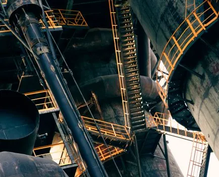
Stay with a gear coupling when the drive is a high-torque kiln, ball mill, vertical roller mill, or crusher where shock loads are common and the gearbox-to-pinion span needs a spacer or 3-part construction; the standard gearbox output arrangements in cement plants, where the industrial gear drives a large pinion through a defined distance, are exactly the geometry that flanged-sleeve and spacer gear couplings were designed for [S1][S2][S4]. Walk away from a gear coupling when the drive is a low-torque, high-dust, lightly loaded conveyor or fan where an elastomeric element will outlast it on contamination tolerance and where the maintenance team will not commit to regular greasing, because an under-lubricated gear coupling in a dusty environment will fail faster than a properly sized elastomer.
Also walk away if the bore sizes, keyways, and balance grades cannot be matched from the replacement brand's catalog, because gear couplings are dimensionally defined components and a mismatch on bore, pilot, or bolt circle is a guaranteed vibration source regardless of how good the new hub steel is [S2][S3]. A useful adjacent reference for plant engineers sizing adjacent mechanical drives is the gear reducer page, and for the concrete-side process context the cement and concrete page covers the application environment these couplings live in.
The next trackable signal is the 2026 maintenance shutdowns at large integrated cement plants in the Middle East and Africa, where FLENDER, KTR, Falk, and Bibby retrofits are converging on interchangeable drop-in gear couplings rather than OEM-only replacements, and the second is the release of updated AGMA service-factor tables for VRM drives, which are likely to push the lower bound of the 1.5 to 3.0 service-factor band upward for high-inertia mill starts [S2][S3].
See also our earlier report, Aluminum Ladder Specs for Interior Finishing: 6061-T6, OSHA Dimensional Criteria, and.