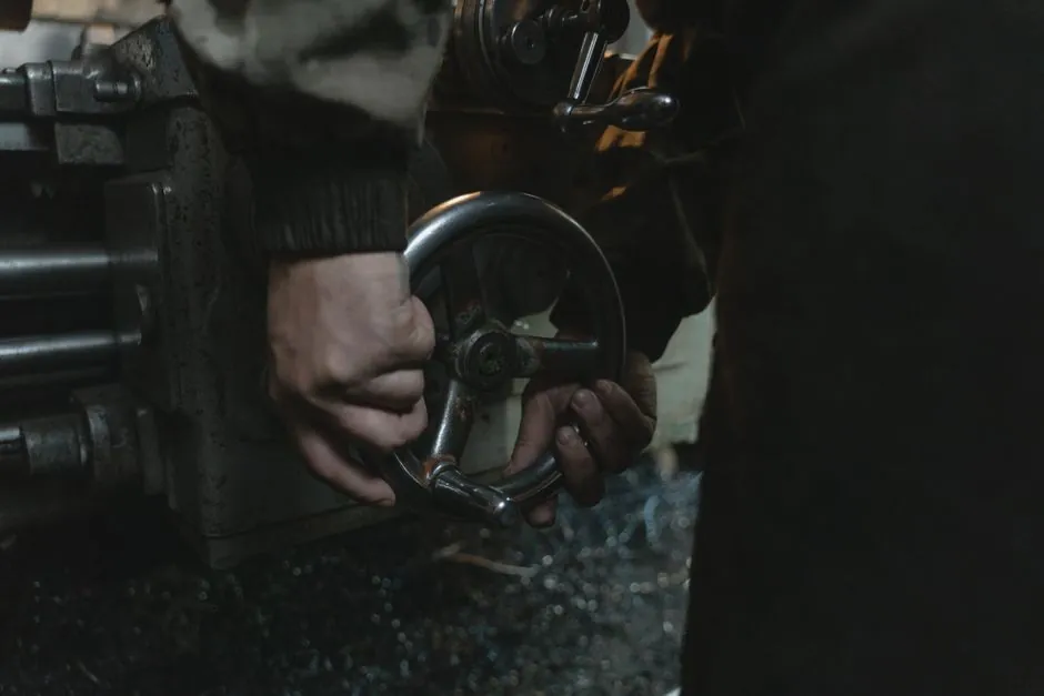
The first specification number to write down is not motor kilowatts, it is peak bite torque at the spindle, because a roughing mill strips gear teeth in a single impact when the coupling is sized on nominal rating [S2]. Hot-strip and blooming mill spindles regularly exceed 100,000 N·m, and a campaign-killing unplanned stop on a hot line has been documented at 26 hours of lost prime production after a single tooth-strip event in a Silesian mini-mill (February 2026) [S2].
Steel-mill gear couplings therefore belong to the all-steel, crowned-tooth, high torsional stiffness family, used in metal-industry rolling and wire-mill service for their high torque-to-size ratio, with general-purpose carbon-steel hubs as the baseline material and forged alloy steel specified for the heavier main drives [S1][S2][S4]. Lubrication interval is 1-2 years depending on duty, and a properly maintained unit reaches 3-5 years of service life, with 5-10 years achievable in benign duty [S4].
Why Steel Mill Duty Is a Four-Way Punishment for the Same Coupling
Steel-mill drives combine shock loads, thermal growth, scale and water contamination, and reversing continuous duty, and any coupling selection must address all four at once, which is why the sizing method starts with shock rather than with power [S2].
Shock loads arrive every time the rolls bite a slab or billet, with roughing and blooming mills seeing torque spikes hundreds of times per shift, and each spike is transmitted through the coupling first [S2]. Drives next to the mill line operate beside steel at 1,000°C or more, so shafts grow and alignment drifts between cold startup and hot rolling [S2]. Mill scale and descaling water attack seals and lubricant, and a coupling that runs clean in a machine shop degrades quickly beside a caster [S2]. Many mill drives reverse every pass and run 24/7, so fatigue accumulates without an idle window for improvised repairs [S2]. A two-year campaign before reconditioning is the realistic performance baseline for a properly maintained gear coupling, with the typical reconditioning cost reported below $0.02 per ton rolled for a well-engineered unit [S1].
Three Drum Gear Coupling Series That Cover Most Mill Drives
Three drum gear coupling series cover the bulk of steel mill drives, each answering a different structural need, and all are machined from forged alloy steel at the heavier end of the range [S2].
GIICL drum gear couplings are the compact, general-purpose choice for mill stands, roller tables, shears, and auxiliary drives, handling high torque while compensating for angular, radial, and axial misalignment [S2]. NGCL drum gear couplings add an integrated brake wheel, making them the standard choice for ladle cranes, charging cranes, and hoists where the brake acts on the coupling [S2]. WGT drum gear couplings insert a removable intermediate sleeve, which is the practical answer for runout tables and any drive where the connected machines cannot be moved for maintenance [S2]. For the heaviest main drives, especially roughing-mill spindles where the angle changes with roll-gap adjustment, a cardan (universal-joint) shaft often replaces the gear coupling entirely, while the gear coupling still owns the motor-to-gearbox connection in the same line [S2].
Sizing the Coupling Against Shock, Misalignment, and Lubrication Life
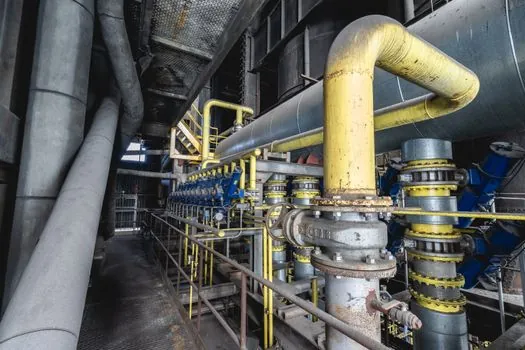
The selection criteria for a steel-mill gear coupling run in a fixed order: peak torque including shock, service factor, misalignment envelope, bore capacity, speed, and lubrication interval, with torsionally stiff all-steel gear couplings sitting at the top of the power-density range across all coupling types [S5].
The two real failure drivers inside a mill gearbox input are shock overload and lubrication breakdown, and both are amplified by misalignment, so a crowned-tooth hub with sealing that holds grease through scale and water exposure is the practical minimum [S2][S4]. Reference designs for roll-stands have shown that a coupling 144-145 mm long with 190-200 mm outside diameter can carry 2,000 N·m rated torque, 3,100 N·m maximum acceleration torque, and 5,500 N·m peak torque when built around a stainless-steel metal bellows, tripling the power density of a standard unit, which is useful when sizing compact mill-stand drives [S3]. Across the broader coupling family, all-steel gear couplings deliver the highest torsional stiffness, while nylon-sleeve gear couplings, grid couplings, and tyre couplings drop progressively down the stiffness scale, and the soft end (S-flex, tyre) is rarely appropriate for mill main drives [S5]. Service life of 3-5 years, and often 5-10 years, is achievable when a steel gear coupling is greased on a 1-2 year cycle and kept within its misalignment envelope, but excessive misalignment shortens life significantly and is the most common avoidable cause of premature failure [S4].
Comparison: Main Coupling Options for Steel Mill Service
Within a steel-mill driveline, the realistic options line up against four decision criteria, and the table below is the working map engineers use before pulling a nameplate. [S2]
All-steel gear couplings (GIICL, NGCL, WGT drum series, and equivalents from FLENDER, KTR, Falk, and Ringfeder) deliver the highest torque density and highest torsional stiffness, accept angular, parallel, and axial misalignment through crowned teeth, and carry a 1-2 year lubrication cycle with 3-10 year life, making them the default for motor-to-gearbox and mill-stand drives [S2][S4][S5][S7]. Cardan (universal-joint) shafts are not gear couplings but displace them on the heaviest roughing and blooming spindles above 100,000 N·m where roll-gap angle changes are large [S2]. Metal-bellows couplings (for example the BK8/1500 family) are backlash-free, torsionally stiff, and compact, and are chosen when installation length is capped near 145 mm and peak torque stays under roughly 5,500 N·m, which is a typical roll-stand gearmotor interface rather than a main-mill spindle [S3]. Grid, jaw, tyre, and S-flex couplings sit lower in torsional stiffness and torque capacity, and are usually reserved for auxiliary rolls, fans, and pumps outside the main mill stand [S5]. gear coupling selection for mining drives follows a closely related logic on shock and service factor, which is useful reference when a mill driveline is also fed by a mine or sinter plant.
Real Use Cases: Rolling Stands, Cranes, Caster Runouts, and Roll Forming
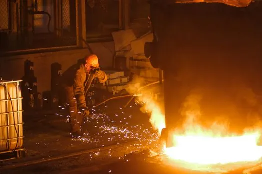
Beyond main-mill spindles, gear couplings sit in the connecting links on the gear reducer input of roller-table drives, in ladle and charging crane hoist gearboxes where NGCL brake-wheel versions dominate, and in shears and auxiliary drives that share the same scale and heat environment as the main stands [S2].
Roll-forming lines further downstream run at up to 200 m/min and demand repeatability from the driveline, so couplings on each roller station are typically compact bellows or gear types matched to the gearmotor output, with peak torque defined by the acceleration profile of the strip rather than by steady-state power [S3]. On a hot rolling line, a single coupling failure cascades through the furnace, caster queue, and campaign schedule, which is why experienced mills specify couplings conservatively, hold critical spares on site, and use the industrial gear train as a system rather than a chain of independent components [S2]. For drives feeding a gear pump or hydraulic power pack on a mill auxiliary, the coupling choice is usually a smaller all-steel gear unit on the same lubrication and misalignment logic as the main drive [S4][S5].
Common Failure Modes, Maintenance Traps, and Standards Background
The dominant failure modes in service are tooth stripping from shock overload, premature wear from contaminated or lost lubricant, and fatigue cracking driven by misalignment outside the design envelope, with a helical gear reducer input coupling typically the first component to show the symptom [S2][S4].
Two maintenance traps are repeatable across the literature: a superior seal design prevents excessive grease loss, and well-engineered components do not require premature replacement, so the difference between a two-year reconditioning campaign and an unscheduled stop is largely about seal quality, metallurgy, and alignment discipline rather than about the catalog torque rating [S1]. A coupling clutch variant, where torque limiting is integrated, is worth specifying on roll-stand drives where a strip jam must not strip the upstream gearbox, and it is the standard tool for protecting a gear coupling on any drive exposed to bite impact [S3][S7]. Generic mill standards reference (such as vendor selection guides for FLENDER, KTR, Falk and equivalent makes) cluster around torsional stiffness class, lubrication interval, and misalignment envelope, and the practical rule of thumb is to size on shock with a healthy service factor, then verify bore, speed, and thermal growth before release [S5][S7].
Trackable Signals for the Next Sizing Cycle
Two signals are worth watching into late 2026: vendor-published replacement guides for FLENDER, KTR, and Falk patterns in steel-mill service, and any field-data release on NGCL brake-wheel coupling life in ladle-crane fleets, since both will tighten the realistic service-factor numbers used in mill engineering. [S1]