Fuel cell stack production capacity in 2026 is sized against three concrete dials: a PEMFC stack envelope that runs 50 W to 25.6 kW per module [S3][S2], a high-temperature SOFC/SOEC range of 2.1 to 4.1 kW per 120-cell AERIE unit at 650 to 750 C [S5], and a Clariant HyProGen catalyst line that covers desulfurization, reforming, water-gas shift, CO purification, and off-gas combustion across LPG, natural gas, methanol, and ammonia reformer feed paths [S8].
For a 2026 line build the planner has to match stack chemistry to balance-of-plant (BOP) before counting cells, because the temperature class of the stack dictates the reformer train, the humidification loop, and the heat-recovery envelope around the BoP side [S1][S8].
Stack chemistry and operating envelope: how the four families map to capacity
PEMFC stacks are the low-temperature workhorse for mobile and stationary power, with stack rated output commonly listed at 1.4 to 2.0 kW in a closed-cathode air-cooled format using titanium separators and a 3,000-hour warranty life for unmanned and portable use [S6]. Proton Motor's Gen 4 family extends the PEMFC envelope to a nominal 3.0 to 25.6 kW per module, with a new manufacturing robot targeted to add 5,000 units per year of capacity [S2].
MCFC and SOFC sit at the high-temperature end: MCFC operates at 650 C and above, can accept fuel without an external reformer, and is penalised by longer ramp rates tied to even temperature distribution across the cell [S1]. SOFC extends further to 650 to 1,000 C and can convert a wide range of fossil fuels, which is why the AERIE SOFC/SOEC stack runs at 650 to 750 C with 80% fuel utilisation and 20% air utilisation at the cell level [S1][S5]. PAFC at around 200 C remains the most mature commercial type, with a typical lifetime near 10 years [S1].
Stack sizing math: from unit nameplate to system nameplate
Every stack capacity model uses the same identity: Total System Nameplate (kW) = Unit Nameplate (kW) x Number of Units, and the minimum system output scales the same way against a unit-level minimum output expressed as a percentage of nameplate or in kW [S1]. For PEMFC at the small-format end, Anabond's 20-cell stack delivers 14 V at 35 A on H2/air with 90% humidification on both sides, 60 C operating temperature, water cooling, ambient pressure, and a stack footprint of 190 mm long by 245 mm deep by 125 mm high at 12.5 kg [S3].
For SOFC, the AERIE 120 delivers 2.1 to 4.1 kW from 120 unit cells at 103 to 152 V DC and 20 to 40 A, while the NEST 10 small-format stack delivers 179 to 346 W from 10 unit cells at 8.6 to 12.6 V DC and the same 20 to 40 A current window [S5]. Both SOFC platforms share a 195 x 186 mm cell footprint, so capacity scaling is done by cell count and current rather than by plate area [S5]. EKPO's NM12-twin PEMFC stack module wraps the cell stack with a media supply module in plastic that already integrates pressure and temperature sensors, which removes a layer of BOP integration work on the line [S4][S7].
BOP and process-gas train: where the 2026 line spends its capex
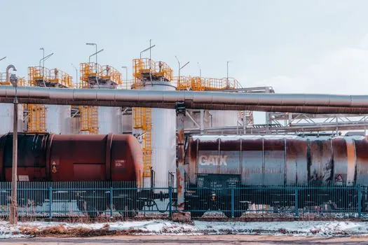
Outside the stack itself, the 2026 line build is dominated by the reformer and gas-cleanup train. Clariant's HyProGen platform covers desulfurization, reforming, water-gas shift, CO purification, and off-gas combustion catalysts in one product line, and is qualified across LPG, natural gas, methanol, and ammonia fuel-cell feed paths with more than 50 years of industrial catalyst heritage behind it [S8].
For PEMFC, the BoP side is dominated by air delivery, hydrogen recirculation, and thermal management, with the EKPO NM12-twin demonstrating that pressure and temperature sensing are commonly integrated into the stack media module rather than added downstream [S4][S7]. For high-temperature stacks, the BoP conversation shifts to heat recovery, off-gas combustion, and stack thermal management at 650 to 1,000 C, with the SOFC operating envelope being the main reason a line planner accepts a longer ramp-rate penalty in exchange for fuel flexibility [S1].
Process instrumentation spec gates for the 2026 line
Every fuel cell stack module that ships in 2026 carries a pressure transmitter and a temperature channel in the media module, and the hydrogen feed line also needs a flow meter sized for 1.5 to 3.0 stoichiometric flow windows typical of small-format PEM stacks [S3][S4]. The off-gas combustion train downstream of the reformer adds a flow meter node for the post-water-gas-shift stream, and most skid builders also bring in a load cell for stack clamping-force verification on the assembly fixture.
For SOFC/SOEC lines, the temperature window is wider and the gas composition window is tighter, so the pressure transmitter spec is governed by stack inlet pressure at 650 to 750 C operating temperature, and the flow meter spec on the air side is set by the 20% air utilisation target at the cell [S5]. Hydrogen flow on PEMFC is commonly held at 1.5 stoichiometric and air at 3 stoichiometric, with both numbers entering the BoP instrument sizing as the design minimums [S3].
Production-rate signals: how the line plan converts stack count into annual output

Proton Motor's Gen 4 capacity expansion, built around an automated manufacturing robot, is targeted to add 5,000 fuel cell units per year, which sets a concrete reference point for what one robotic cell on a PEMFC line is expected to deliver at 3.0 to 25.6 kW per stack [S2]. Anabond's 50 to 1,000 W PEMFC stack range shows the small-format end of the same product family, where a 20-cell stack running at 14 V and 35 A gives 490 W of rated output from a 12.5 kg assembly [S3].
On the high-temperature side, AERIE 120 at 2.1 to 4.1 kW per 120-cell stack gives a cell-level power density near 17 to 34 W per cell, and NEST 10 at 179 to 346 W over 10 cells shows 18 to 35 W per cell, so a planner converting cells-per-shift into kW-per-shift can use roughly 20 to 35 W per SOFC cell as a rule of thumb, with the industrial valve count on the gas train set by the number of feed paths rather than by stack count [S5].
Comparison table: PEMFC, MCFC, PAFC, SOFC against capacity-planning criteria
Across the four chemistries, PEMFC at 60 to 80 C covers the low-temperature envelope with 50 W to 25.6 kW modules and 3,000-hour warranty life on closed-cathode air-cooled designs [S2][S3][S6]. PAFC at around 200 C offers the most mature commercial track record with a lifetime near 10 years, but at a lower power density than PEMFC and SOFC [S1]. MCFC at 650 C and above removes the external reformer but pays with longer ramp rates and lower durability [S1]. SOFC at 650 to 1,000 C accepts the widest fuel range, runs at 20 to 40 A per 120-cell stack at 103 to 152 V DC, and can be flipped into SOEC electrolysis mode for hydrogen production at 3.6 Nm3/hr per AERIE 120 unit [S1][S5].
On sourcing lead time, PEMFC and PAFC benefit from MEA, membrane humidifier, and titanium separator supply chains that are already multi-vendor, while MCFC and SOFC remain dependent on a narrower set of stack makers and on catalyst suppliers with long qualification cycles [S1][S3][S5]. Clariant's HyProGen line is one of the few reformer-catalyst packages that explicitly covers LPG, natural gas, methanol, and ammonia feeds in a single product family, which is why it shows up on most 2026 BOP bills of materials [S8].
Limits, failure modes, and what the 2026 line planner should not assume
Fuel cell stack capacity planning is not a clean linear scale-up. MCFC's longer ramp rate is a direct consequence of needing even temperature distribution across the cell, and any line plan that treats MCFC as a drop-in for PEMFC at the system level will under-size the thermal management skid [S1]. The 3,000-hour warranty life on a closed-cathode air-cooled PEM stack is for the stack only, not for the BoP, and BoP lifetime is governed by humidifier, flow meter, and pressure transmitter drift rather than by stack degradation [S6].
For SOFC, the 80% fuel utilisation and 20% air utilisation numbers are cell-level targets, not system-level turndown, and the 10.4 kW SOEC mode on the AERIE 120 only holds when the stack is fed with a steam conversion ratio near 80% and a hydrogen ratio near 20% [S5]. On the sourcing side, the assumption that PEMFC capacity can be lifted by simply adding more robots is only valid if MEA supply, bipolar plate supply, and stack assembly fixtures are sized in lockstep, and the 5,000-units-per-year target at Proton Motor is a stack-assembly number, not a full system number [S2][S4].
For related equipment planning, the Fuel Cell Stack Assembly Equipment: Spec Map and Selection Guide covers fixture and clamping-force spec gates that feed directly into the load cell choice on the line, while the BMS Production Capacity Planning: Line Sizing, Cell Format, and Gigafactory Specs piece applies the same station-by-station capacity logic to the battery side of the same plant build. For instrument selection downstream of the stack, the Smart valve positioner: accuracy, diagnostics, and the trade-offs you actually pay for reference maps to the reformer and off-gas combustion valves on the BoP train.