
Shell molding heats a metal pattern before resin-coated sand is introduced onto the heated pattern plates to create a hardened shell [S1].
Gas systems suit high-load plates with rapid recovery, while electric systems favor controlled low-to-medium loads where electrical capacity, element life, and localized switching remain manageable [S3].
Define the Heating Duty Before Choosing a Fuel
A shell pattern heater is not a general-purpose comfort heater. Its job is to bring a metal pattern to a controlled working temperature, maintain that temperature during sand contact, and recover after each shell-forming cycle [S1][S5].
The process starts with a heated metal pattern, after which resin-coated sand is introduced so that a thin shell can form and harden around the pattern [S1].
Pattern size and weight therefore determine the real load. A small laboratory pattern may need little installed power, while a full-size production pattern adds mass, exposed surface area, heat loss, and a larger demand for recovery after switching. A credible comparison must record plate material, dimensions, mass, target temperature, tolerance, cycle time, and duty hours rather than rely on burner or heater catalog ratings alone.
Compare Gas and Electric by Four Decision Criteria
Gas heating is the stronger option where the pattern plate has high thermal mass, rapid recovery is required, or electrical infrastructure is unavailable. Its disadvantages include combustion-system complexity, exhaust or flue routing, fuel availability, burner controls, and local combustion-safety provisions [S3].
Electric resistance heating gives direct, compact, and controllable plate heating with no on-site fuel train. It is the better choice for smaller or medium plates operated within a stable cycle, provided the power supply, element rating, heat distribution, and maintenance access are adequate [S3].
This is a criteria-based comparison, not a universal ranking: gas normally wins on load and recovery, while electric normally wins on installation simplicity and direct control. For context on how these decisions appear in other industrial thermal equipment, Gas-Fired vs Electric Resistance Crucible Furnace: Spec Comparison provides a related method for comparing fuel systems by capacity, control, and operating constraints.
Temperature Uniformity Drives Casting Quality
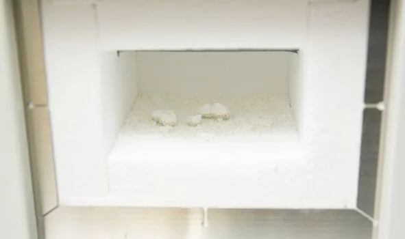
The shell must cure consistently around the entire pattern, because local temperature variation can produce uneven shell thickness, weak bond at cold areas, and inconsistent mold dimensions [S1][S2]. A hot plate at the correct average temperature can still be the wrong heater if its center-to-edge variation exceeds the process window.
Electric heating tends to suit controlled applications because resistance elements can be distributed across the plate and governed by control cycles [S3]. Gas heating can also provide high output, but its heat distribution depends on burner placement, flame geometry, combustion settings, recirculation, shielding, and the pattern’s thermal conductivity. Neither fuel label guarantees uniformity.
Acceptance testing should be based on mapped plate temperature, not a single controller display. Map the heated face at the center, edges, corners, and areas near draft or sand-release features. Record the warm-up period, temperature variation under sand load, recovery time after a shell cycle, and overshoot during burner or element cycling. The acceptable limits must come from the mold supplier or established trial data, because the research does not establish a universal pattern-plate tolerance.
Match the System to the Shell-Molding Machine
Pattern heating must integrate with the shell molding machine, including shell dwell, inversion, sand release, and the interval before the next heating cycle. Gas and electric systems also occupy different space and service envelopes: a gas package includes burner and fuel components, while an electric package includes heaters, power distribution, contactors, and thermal protection. [S4]
Gas is generally the more practical choice for large, continuously operated tooling where each cycle removes a meaningful heat load. Electric heating becomes more attractive when the pattern is compact, cycle frequency is controlled, and the electrical service can handle the connected load and startup demand. A production molding line should not accept either system until recovery time has been matched to the indexed cycle.
For manual or small-scale work, the economic threshold is often set by tooling utilization rather than peak temperature alone. An underused electric heater can have the lower installed cost, but a gas system may recover the heating requirement more quickly if production rises sharply. Conversely, a permanently installed gas train adds commissioning and maintenance burden when annual operating hours are low.
Use Cases and Equipment Boundaries
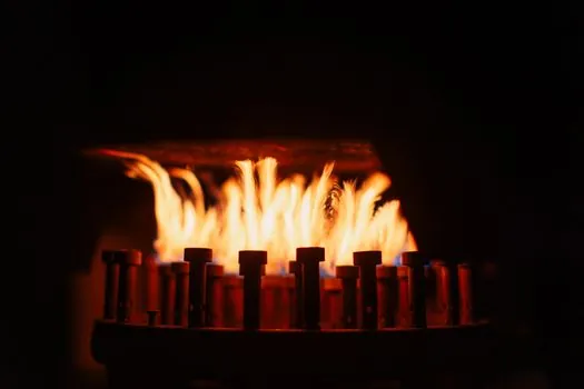
Gas heating is appropriate for large metal patterns, extended production runs, and installations where a high heat-release rate must restore the plate temperature rapidly. Electric heating is appropriate for smaller or medium plates, laboratory and lower-duty cells, and plants with reliable electrical capacity but limited fuel infrastructure [S3].
Neither option is the right choice for uncontrolled heating of a pattern made from an incompatible material. Shell molding commonly uses machined iron or steel patterns, while graphite can be used for reactive metals [S5]. The pattern specification, including thermal expansion and maximum temperature, must therefore be confirmed before either heater is selected.
The process itself limits some shell-molding applications. Published comparisons note that shell molding is generally less suitable for very large or heavy castings, with examples given around 500 mm length or 30 kg, because of shell and core machine limitations [S4]. This equipment boundary matters because a large casting may also imply a large pattern and unusually high heating demand.
Safety, Maintenance, and Failure Modes
Gas failures typically involve flame failure, loss of ignition, incomplete combustion, blocked or unsuitable flue arrangements, and uneven heat distribution. Electric failures typically involve element burnout, contactor or control faults, supply limitations, and local hot spots caused by uneven element placement or degradation [S3].
For a gas installation, specify flame supervision, proven purge or interlock arrangements, suitable fuel and exhaust connections, and an interlocked shutdown path. For an electric installation, specify element watt density, terminal protection, over-temperature protection, contactor sizing, and an appropriate electrical protection arrangement. These are functional requirements; the supplied research does not establish a governing standard number for a specific safety design.
Insulation is relevant to both systems. It limits standby heat loss, but it must not obstruct pattern ventilation, sand release, maintenance access, or the temperature measurement used for control. A thermocouple should check the actual pattern face because heater outlet air temperature does not prove that the plate has reached the 230–340 °C process range [S5].
Specify and Verify the Heating Package
Specify the system using measured operating data: plate material, dimensions, mass, target temperature, acceptable uniformity, shell cycle duration, production hours, fuel or electrical availability, and recovery requirement. Then verify uniform heating over more than one complete cycle, including startup, steady production, and post-shell recovery. [S4]
Gas wins when high-load recovery and infrastructure independence matter most. Electric wins when direct control and lower on-site mechanical complexity matter most. The decision should remain conditional on plate duty, because neither the 230–340 °C process range nor the claimed advantages of shell molding guarantee that one heating method suits every pattern [S1][S3][S5].