High-pressure die casting routinely fills sections at 1.0–1.5 mm in aluminium alloys, while gravity die casting bottoms out near 3 mm as a practical production minimum [S4][S7].
The shortfall is not a marketing artefact; it is a direct consequence of fill mechanics, alloy head pressure, and skin formation rate. Engineers weighing die casting against gravity die casting for a given geometry need to read the wall-thickness band as a hard process boundary, not a preference.
Two Processes, Two Fill Mechanics
Gravity die casting relies on the hydrostatic head of a poured basin to drive molten aluminium into a preheated steel or iron permanent mold; typical fill relies on a 200–300 °C die and a 650–750 °C pour, with cycle times of 2–10 minutes per shot [S2][S5]. High-pressure die casting injects the same alloy at 150–1200 bar, filling in milliseconds and finishing a cycle in 10–60 seconds [S4]. That pressure differential, not mould material, is the dominant reason one process can hold 1 mm walls and the other cannot.
The fill pressure is what compensates for the rapid skin formation of aluminium on a cold die wall. Once a solidified layer forms across a thin section, gravity alone lacks the energy to break it and feed the remaining cavity; HPDC's injection velocity keeps the leading edge of the metal liquid long enough to complete the fill. This is the same dynamic the die casting die is engineered around: die temperature, venting, and overflow placement exist specifically to sustain that fill front.
Wall-Thickness Ranges Across the Casting Family
Multiple published references converge on a 3 mm practical floor for gravity casting. One process selection guide lists gravity as best suited to 3–10 mm walls versus HPDC's 1–5 mm range [S4]. A separate manufacturing guide places the gravity band at 3–20 mm, with a stated minimum of 3 mm and dimensional tolerance of ±0.3 mm to ±0.5 mm on production parts [S5]. A third reference echoes the 3 mm minimum and notes that HPDC can drive walls down to 1 mm under matched equipment and alloy conditions [S4][S7].
For HPDC specifically, 1.0–1.5 mm is the accepted production minimum for standard aluminium die casting, with thinner sections achievable only when high-flow alloys and tightly controlled die temperature are paired with the press [S7]. Dynacast's design guidance references a typical 2 mm wall for aluminium die casting as a working benchmark, with the thin-wall extreme reserved for shorter flow paths [S1]. The same Dynacast page notes that cast alloys tolerate wall-thickness variation better than plastic because surface tension preserves skin integrity, which is why aluminum die casting machines are specified for parts where HPDC's thinner envelope matters.
Process Comparison on Engineer Decision Criteria

Selection between gravity and high-pressure die casting turns on four measurable criteria: minimum wall, tolerance, porosity, and per-part economics. The published numbers line up as follows: gravity die casting delivers 3–20 mm walls at ±0.3–0.5 mm tolerance with low internal porosity and heat-treat compatibility, while HPDC delivers 1–5 mm walls at ±0.1 mm tolerance with surface finish of Ra 0.8–3.2 μm but trapped gas porosity that blocks T6 treatment [S4][S5].
The economic dimension reinforces the same gap. Gravity casting absorbs moderate tooling cost and runs an annual band of roughly 250–50,000 parts at low-to-medium volume, whereas HPDC demands higher tooling investment amortised across high-volume runs that exceed 200 parts per hour per machine [S4][S5]. When a part sits below 3 mm in any critical section, gravity casting is the wrong envelope and the conversation has to move to HPDC, even at the cost of giving up heat-treat compatibility.
Alloy, Heat Treatment, and Mechanical Integrity
Gravity casting's slower, top-fed fill minimises gas entrapment, producing dense castings that survive T5 and T6 treatment without blistering [S2][S4]. A356-T6 poured by gravity routinely clears 290 MPa tensile, 210 MPa yield, and 4% elongation test-bar minimums to EN 1706, a property envelope that HPDC cannot match in the same alloy because the same trapped gas that holds 1 mm walls expands during solution treatment [S2]. A319 and 6061 are cited as alternative gravity alloys where weldability or elevated-temperature behaviour is needed, with 6061 entering the mix specifically for welded sub-assemblies [S2].
For magnesium and zinc programmes, the same wall-thickness logic applies through a different pressure window; magnesium die casting machines inherit HPDC's thin-wall capability, while gravity magnesium pours follow the 3 mm floor. A Neway reference reinforces the rule from the other side: gravity casting fits parts with thicker wall sections, larger bosses, and load-bearing geometries where riser placement and directional solidification can be planned into the tool, rather than designed around a thin-wall fill limit [S8].
Where Gravity Casting Is the Right Call, and Where It Is Not
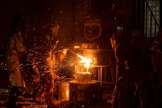
Gravity casting is the right call for structural aluminium parts in the 3–20 mm wall band, weights from 0.1 kg to 100 kg, low-to-medium annual volumes (roughly 250–50,000 pieces), and any geometry that will see T6 heat treatment or welded assembly [S2][S5]. Tilt-pour variants add directional solidification control for thicker sections that would otherwise feed shrinkage porosity, and that variant is described as the more reliable gravity option in the published process guides [S2].
Gravity casting is the wrong call when any functional wall drops below 3 mm, when the production schedule demands more than 200 parts per hour from a single cell, or when the surface finish specification requires Ra below 0.8 μm without secondary machining. In those cases, an die casting machine configured for HPDC is the only published route that holds the 1.0–1.5 mm minimum, and the trade-off against heat-treat compatibility has to be accepted in the same review [S4][S7].
Designing Around the Limit, Not Through It
Engineers who try to push gravity casting below 3 mm usually hit one of three failures: incomplete fill, cold shuts from premature skin formation, or surface laps where the fill front stalls against a frozen layer. None of these are recoverable by adjusting alloy alone; they are fill-energy limits set by the absence of injection pressure [S4][S7]. A DFM review that walks the wall-thickness map section by section, flags anything under 3 mm, and routes those features to HPDC, or to a redesign that thickens the local section, prevents tooling from being cut for a part the chosen process cannot fill.
The two signals worth tracking on a live project are: whether any pilot sample from the gravity cell shows fill-related defects in the thinnest specified wall, and whether T6 blistering appears during the first heat-treat trial if the part was switched to HPDC for thin-wall reasons. Either result is a clear instruction to revisit the wall-thickness allocation before the next tooling revision. For an extended discussion of how process selection intersects with material cost volatility, see the recent sourcing brief on nickel and chromium surcharges stretching alloy steel lead times past seven months, which surfaces a parallel lead-time and specification pressure on adjacent casting supply chains.
Spec-level background on the components involved: gravity die casting machine, die casting, and die casting die.