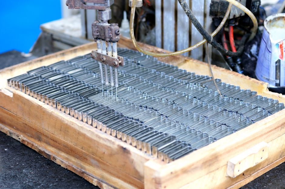
The harmonic reducer (strain-wave gear) production chain resolves into three sub-assemblies — wave generator, flexspline, and circular spline — with the thin-wall flexspline as the dominant cost and quality driver [S4].
Commercial CSG/CSF-2UH-class units are offered in ten frame sizes with gear ratios of 50, 80, 100, 120 and 160:1, while momentary torque up to 200% of the rated 1,450 rpm value is allowed under catalog limits [S2][S6]. For a side-by-side reference of the strain-wave topology, see the harmonic reducer encyclopedia entry.
Bill of Materials and the Three Working Components
A finished strain-wave reducer consists of exactly three load-carrying elements: a rigid circular spline (outer ring, typically 2 teeth more than the flexspline), a thin-wall cup- or hollow-type flexspline with external teeth, and an elliptical wave generator (WG) carrying a thin ball bearing [S3][S4]. The WG bearing — not the gear teeth — is the input; at 2,500 rpm or below the catalog torque equals the 500-rpm rated torque [S6].
Material selection for the flexspline favours high-strength, high-elasticity grades (a typical route uses elastomer-polymer bushings combined with metallic-elastic bodies) so the part can survive millions of elastic deformation cycles at the elliptical-cam interface [S4]. Compare this with the much stiffer ring architecture of a cycloidal reducer, which uses eccentric lobes and pin rollers instead of tooth elastic deformation. DHSG-H and DHSG-S precision series housing dimensions for sizes 14/17/20/25/32/40/45 are tabulated in millimetres, with input/output axial tolerances listed against each frame size [S5].
Flexspline Forming, Heat Treatment and Material Routes
Process-wise, the manufacturing sequence for harmonic reducers runs: circular-spline blank machining → gear hobbing/shaping → heat treatment → grinding → flexspline cup drawing or welding → tooth cutting on the thin wall → heat-treatment of the thin-wall flexspline → wave-generator bearing assembly → run-out and backlash measurement → life test [S4].
Patented and published process routes include dedicated heat-treatment cycles for thin-wall flexible gears (e.g. CN109837379B, granted 2020-11-24 to Zhejiang Laifu Harmonic Drive) and surface-treatment methods for wave-gear reducer teeth (JP6530873B1, granted 2019-06-12 to Fuji Kihan). For bulk-metallic-glass flexsplines, US11859705B2 (California Institute of Technology, granted 2024-01-02) describes rounded strain-wave geometries that exploit the high elastic limit of amorphous alloys — useful for raising tooth-root fatigue life beyond what 40Cr or bearing-steel cups can deliver. Designers evaluating exotic flexspline materials should weigh these against conventional additive-manufacturing material feedstocks used in the broader precision-motion supply chain.
Tooth Profile Control: Why "S" Geometry Matters
Tooth profile is the single biggest determinant of harmonic-reducer life and torsional stiffness — the Harmonic Drive "S" tooth profile, introduced by Harmonic Drive in 1988, is the benchmark reference geometry used by most modern commercial strain-wave gears. [S1]
Conjugate action between the flexspline (external teeth) and circular spline (internal teeth) generates a roughly 30–40% tooth-mesh overlap that gives strain-wave gearing its shock tolerance and near-zero backlash [S4]. The "S" profile then improves contact ratio, life, and torsional stiffness versus the original Musser 1955 patent geometry, while still allowing flexspline wall thickness down to ~0.3–0.5 mm in cup designs. The same S-tooth concept is reused in derivatives such as the DHSG-H hollow-series and DHSG-S standard-length cup series, both of which share a common circular-spline module family [S3][S5].
Input Coupling Architectures and Backlash Targets
There are four canonical input-connection types in current production: Type I (standard, flat-key to cam inner bore), Type II (cross-slider coupling), Type III (cylindrical-hollow, screw-fastened to a hollow cam), and Type IV (solid shaft integrated into the cam) [S3]. Type II is the default for high-speed robot joints because it tolerates small parallel/angular misalignments between motor shaft and cam without inducing side-load on the WG bearing [S3].
Catalog backlash for precision harmonic series sits in the 0.033–0.118 mm band across sizes 14–45 when measured at the output, with smaller frame sizes achieving the tightest 0.033–0.040 mm figure [S5]. For frame 32 DHSG-H versus DHSG-S, backlash values are 0.038 mm and 0.041 mm respectively, illustrating how the standard-length cup variant trades a few microns of precision for shorter axial envelope [S5].
Acceptance Testing: Accelerated Life, Backlash and No-Load Run-Out
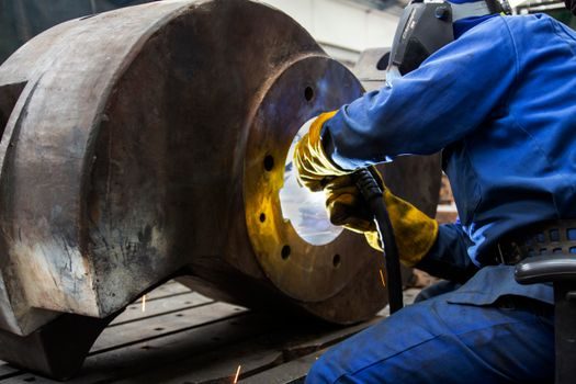
OEM end-of-line testing for harmonic reducers combines three checks: no-load low-voltage run-out (concentricity and waveform symmetry of the WG orbit), loaded backlash at rated torque, and accelerated-life sampling on a torque-overload rig [S1][S6]. The 2022 Journal of Mechanical Science and Technology framework calibrates an accelerated life test against torque amplitude, extrapolating operational robot-joint life from high-stress short-duration runs [S1].
Two catalog rules govern torque margins: torque at 2,500 rpm or less equals torque at 500 rpm, and momentary allowable torque reaches 200% of the 1,450 rpm rated value for short pulses [S6]. Cross-roller-bearing life and maximum moment load must be calculated separately from gear-tooth life — a frequent procurement error is to specify only the gear rating and miss the bearing L10 limit [S6]. Finite-element validation of thin-plate flexsplines now uses quadratic tetrahedral elements with mesh refinement biased to the high end (~10% bias) and minimum element size 20% of the average, a 2026-published modelling recipe in the International Journal of Precision Engineering and Manufacturing.
Comparison of Main Harmonic-Reducer Form Factors
The three dominant physical formats trade compactness, stiffness and cost as follows. Cup-type standard (DHSG-S) gives the shortest axial length and the lowest mass for a given ratio, making it the default for collaborative-robot wrist axes; cup-type hollow (DHSG-H) routes cables or a tool shaft through the centre bore at the price of slightly higher backlash (frame 32: 0.041 vs 0.038 mm) [S3][S5]. Short-length Type I units (Code "D") save roughly 15–20% axial length versus standard-length Type I units (Code "S") and are preferred when arm-segment packaging is the binding constraint [S3].
For higher ratios the 120:1 and 160:1 gearing offered in the CSG/CSF-2UH family is typically paired with Type III hollow cam input so a through-bore motor cable or pneumatic line can pass the reducer axis; for 50:1 and 80:1 ratios in the same series, Type II cross-slider input is more common [S2][S3]. In robot-joint applications, RV reducers compete at the base axis where shock load is high, while harmonic units dominate the wrist axes where zero backlash and high ratio in a small envelope matter more — a split the cobot cell-stack mapping article treats in detail [S2].
Limits, Failure Modes and Sourcing Constraints
Three failure modes dominate field returns: flexspline tooth-root fatigue, wave-generator bearing brinelling, and cup weld-line cracking on hollow-type units operated above ~70% of momentary torque rating [S1]. Each is sensitive to heat-treatment quality on the thin-wall flexspline, making the CN109837379B-class processes a direct lever on warranty cost.
Sourcing constraints concentrate in the flexspline blank and the wave-generator bearing; the cup-drawing step, the S-tooth grinding step, and the matched elliptical-cam bearing set are the three gates that determine lead time for new frame sizes [S4]. A procurement team should verify that the supplier's published harmonic-reducer line includes S-tooth geometry, can document a heat-treatment process for thin-wall flexible gears, and provides per-frame no-load run-out plus loaded-backlash reports — without those three artefacts, reliability at 200% momentary torque cannot be claimed [S6]. For adjacent process context on the automation layer that assembles these reducers into robot joints, see the related coverage on HBM smart manufacturing lines and on AI accelerator packaging flows, which document similar thin-wafer-handling disciplines transferable to flexspline production [S4].