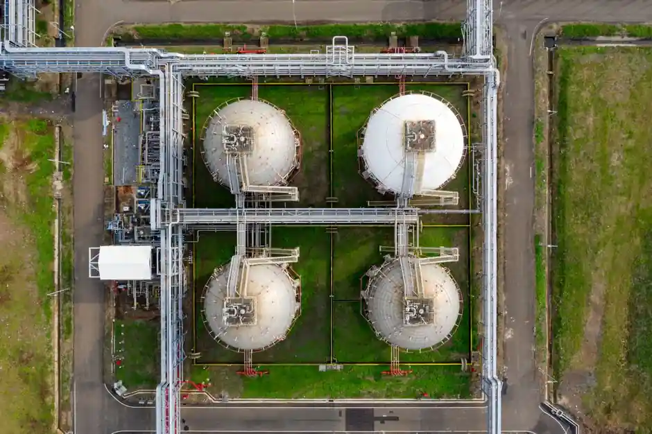
Rate-compensation mechanical heat detectors in ATEX/IECEx-approved housings are the workhorse for hydrocarbon process overheat detection, with factory-set activation temperatures spanning 60°C to 385°C and 316 stainless steel wetted construction as the default for sour service [S1][S4].
The oil and gas envelope is wider than almost any other industrial setting: offshore platforms swing from roughly -20°C Arctic exposure to 50°C desert heat within seasonal cycles, and a single-degree deviation on a refinery hot spot can cost thousands of dollars in lost throughput [S6]. Selection therefore starts with matching the detector family, the protection concept, and the temperature class to the worst-case process and ambient conditions, not with brand preference [S5].
Hazardous Area Classification and Temperature Class Mapping
Under IEC 60079 zoning, Zone 0 covers atmospheres that are hazardous continuously or for long periods, Zone 1 covers atmospheres likely during normal operation, and Zone 2 covers atmospheres unlikely during normal operation and short-lived when they occur; Class I Div 1 and Div 2 under NEC 500/505 map roughly onto Zones 1 and 2, with gas groups A through D in the US system (Group B hydrogen, Group D propane) paralleling IIA, IIB, and IIC internationally [S5].
Temperature classes T1 through T6 cap the maximum surface temperature of the detector, with T6 limited to 85°C; pairing the wrong class against a low-auto-ignition gas such as hydrogen (IIC) is a specification defect, not a field-adjustable parameter [S5]. For combined hydrocarbon and hydrogen service on a process module, a T4 or T5 detector with Ex d flameproof or Ex e increased-safety protection is the common configuration, while Ex ia intrinsically safe variants are specified for the lowest-energy loops where loop integrity is verifiable [S3][S5].
Heat Detector Families: Rate-Compensation, Fixed-Temperature, and Rate-of-Rise
Fenwal Detect-a-Fire units use a rate-compensation method that triggers at the predetermined setpoint regardless of fire growth rate, suppressing false trips from brief ambient swings while still responding inside seconds to a fast-rate fire; the same construction has been in service for over 75 years with hermetically sealed, tamperproof, self-restoring stainless steel elements and no replaceable parts [S4]. Fixed-temperature and rate-of-rise devices are simpler and cheaper but trade off either nuisance immunity or fast-flame response, which is why rate-compensation dominates overheat detection on rotating equipment and turbine enclosures [S1][S4].
Ceiling-height derating is hard physics: a 9 m ceiling cuts heat-detector effectiveness roughly 40% versus a 3 m reference, and beyond 10.5 m fixed-temperature detection is generally not accepted for life-safety signalling under BS 5839-1, which is why process-area detectors on offshore modules are routinely specified as point-of-contact devices on bearing housings, casing surfaces, or ductwork rather than as ceiling-mount smoke equivalents [S7]. For comparison against heat detector families on three decision criteria, see the table below.
Housing Materials and Ingress Protection for Harsh Service
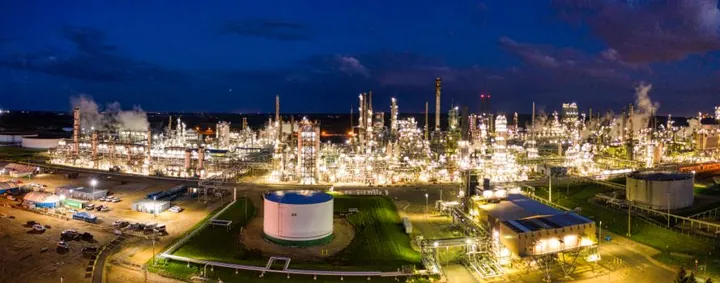
For Zone 1 hydrocarbon service, ATEX/IECEx-approved detectors are offered in marine-grade alloy (intrinsically safe variant for oil and gas), glass-reinforced plastic (Ex em/Ex ia UL variant), and diecast aluminium or 316 stainless steel (Ex d variant) [S1][S3]. IP66 weatherproof housings extend the activation window down to a 60°C to 232°C band for outdoor or washdown locations, while IP66/IP67 is the standard for line-of-sight flame detectors in the same envelope [S1][S2].
316 stainless steel is the conservative default for wetted and exposed parts where sour service (H2S), chloride-rich marine atmosphere, or process contamination is in scope, consistent with the same material discipline applied to oil seal and process-gasket selections in hydrocarbon Rotating Equipment. A Flurocarbon protective coating is an option for highly corrosive environments such as spray booths and offshore splash zones, and double-thread or extended-lead variants allow the detector to be positioned into the optimal airflow without re-routing conduit [S1].
Pairing Heat Detection with Flame Detection for Full Coverage
Heat detectors are the right call for overheat on bearings, casings, and ductwork, but they are blind to an open-flame hydrocarbon event in clear air; a UV/IR dual-spectrum flame detector such as the Honeywell FS-TSGAS-1624 sees a 1 m² n-heptane fire at up to 25 m with a sub-5 s response, runs on 16 to 32 V DC, and outputs 4-20 mA plus relay into FSC, Safety Manager, or Experion PKS [S2]. The same unit operates from -55°C to +75°C, weighs roughly 2.0 kg, carries ATEX/IECEx Zone 1 and Zone 2 plus FM approval, and rejects arc-welding, lightning, and solar false alarms through dual-spectrum correlation [S2].
Where flammable vapours, LNG/LPG, and hydrocarbon gases are handled, the typical architecture is point-of-contact heat detection on equipment plus line-of-sight flame detection in the open process area, with aspirating smoke or linear heat cable added where smouldering electrical faults in cable trays are a concern: those faults can produce toxic smoke for hours without ever crossing 57°C, which is why EN 54-20 and NFPA 72 require smoke or aspirating detection in those locations rather than heat alone [S7]. Crowcon's flame detection guidance reinforces that flame detectors are an early-warning layer for fuels, gases, and hot work, complementary to heat and smoke layers rather than a substitute [S8].
Selection Workflow and Common Failure Modes
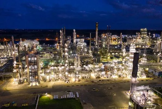
A defensible specification for an oil and gas heat detector pins down six fields: (1) IEC 60079 zone or NEC class/division/group, (2) temperature class T1 to T6 matched to the gas auto-ignition, (3) activation setpoint in °C with rate-compensation preferred for overheat loops, (4) housing material and IP rating matched to atmosphere, (5) output protocol compatible with the DCS or F&G controller, and (6) third-party certificates (ATEX, IECEx, FM, UL) traceable to the specific model code [S3][S5].
Common failure modes to design out: specifying a fixed-temperature only device on a high-ceiling module and losing 40% effectiveness at 9 m, choosing a non-rate-compensation detector in a turbine enclosure where ambient swings cause nuisance trips, using a non-316 housing in sour H2S service, and pairing a heat detector alone with a cable-tray run where smouldering faults dominate the fire risk profile [S7]. On the construction machinery and equipment side of an oil field, the same rate-compensation logic carries across to engine bay and hydraulic-pack overheat loops, which is why the Detect-a-Fire concept is shared across both fixed and mobile installations.
Sourcing, Standards, and Verification
Third-party certification is non-negotiable: ATEX 2014/34/EU for the EU, IECEx for the rest of the world, FM and UL for North America, and marine approvals (e.g., DNV, Lloyd's) where offshore classification rules apply, all stamped on the nameplate against the specific model code rather than the product family [S1][S3]. Honeywell's FS-TSGAS-1624 datasheet cross-references compatible equivalents from Det-Tronics (FL3100H, X3301), MSA Safety (FlameGard 5 MSIR), Spectrex (Talentum UV/IR), and Emerson (Rosemount SFL-3000), which is useful for second-sourcing but never a substitute for verifying electrical, mechanical, and certification compatibility against the live datasheet [S2].
Two trackable signals to watch: any revision to IEC 60079-0 or IEC 60079-1 that tightens surface-temperature or flameproof-gap requirements, and the next round of NFPA 72 spacing guidance for high-ceiling process modules, both of which will reset detector spacing rules across offshore and onshore oil and gas sites. Specifiers who lock down zone, gas group, temperature class, setpoint, housing, and protocol before model selection will avoid the most expensive rework: replacing a housing that cracked from vibration, a transmitter that drifted on a sour-gas line, or a detector that nuisance-tripped on a turbine enclosure.
Background reading: Busway sizing and selection: the engineer's field workflow.