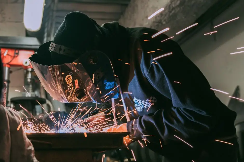
Welding shops are the textbook hostile environment for smoke and UV flame detection, and process engineers routinely swap in fixed-temperature or rate-of-rise heat detectors at the fume extractor or filter housing to keep nuisance trips under control [S1][S2].
Selection pivots on three numbers: the detector setpoint (commonly 88°C / 190°F for oily-product robotic welding), the housing rating (IP65 minimum for spark and coolant exposure), and the actuation type (normally open, volt-free contact tied to a fire-suppression panel) [S5].
Why Smoke and UV Flame Detectors Fail in Welding Cells
Smoke detectors respond to airborne particulates, so welding fume, grinding dust, and cutting-table aerosols force unwanted alarms, which is why NFPA-style guidance steers them away from shops, kitchens, and garages [S4]. Optical (photoelectric) smoke units in particular scatter-trip on sub-micron fume that is a normal byproduct of GMAW and flux-cored arc welding, generating the false-alarm fatigue that gets detectors deliberately disabled.
UV flame detectors trip directly on the welding arc itself, a single-phase 200-400 nm emission that is indistinguishable from a real flame, and they are also degraded by oil and grease films on the lens, which is the most common field failure mode [S1]. Single-frequency IR units see the cutting torch flame just as readily, so oxy-fuel and plasma tables rule them out alongside UV; the only flame technology that survives in some welding cells is dual- or multi-band IR/IR or UV/IR with voting logic [S2].
Heat Detector Operating Principles Relevant to Welding
Fixed-temperature heat detectors signal when the sensing element reaches a calibrated threshold, while rate-of-rise units trip on a temperature slope exceeding a set °C-per-minute value, and combination units do both, tolerating slow ambient drift while still catching fast-onset fires [S1]. Combination fixed + rate-of-rise is the conservative default for a robotic welding cell because it rejects the slow 0.5-1°C/min shop-warmup curve but still triggers within seconds of an in-filter fire.
Available sensing elements span fusible plastic tubing, fusible optical fiber, bimetallic strip, fusible link under spring tension, and pneumatic quartzoid bulbs; spot-type electronic units with a thermistor or bimetallic strip dominate new welding-fume installations because they integrate cleanly with 24 VDC fire panels [S1]. For welding-fume filter housings, the sensing probe is typically a high-alloy steel tube (15 mm diameter, 115 mm long) threaded into an IP65 aluminum junction box, with a 190°F (88°C) trip and a +14/-13°C tolerance band, matching the Lincoln Electric Guardian specification [S5].
Selection Criteria: Setpoint, Rating, and Interface
Setpoint must clear the worst-case steady-state operating temperature at the detector location. Inside a fume-extractor housing downstream of a spark arrestor, normal operating skin temperatures stay under 60°C, so an 88°C fixed setpoint gives roughly 25-30°C of headroom; specifying 57°C (135°F) instead guarantees nuisance trips during long MIG weld cycles on hot steel [S5].
Electrical rating must match the fire-panel input. The Guardian-class detector switches 5.0 A at 126 VAC or 2.0 A at 24 VDC, with a normally open contact that closes on trip, so the panel sees a short-to-supervisory rather than a powered loop, which simplifies SIL evaluation on the suppression solenoid [S5]. For a typical comparison against the main detector families used near welding, the criteria line up as follows:
Optical smoke: fastest on smouldering fires, but trips on fume and dust; unsuitable for welding cells [S4]. Fixed-temperature heat: tolerant of fume and dust, setpoint-selectable, slower response, ideal for filter housings and cutting tables [S1][S5]. Rate-of-rise heat: fast on open fires, tolerates slow ambient drift, less suited to locations with normal rapid temperature swings [S1]. UV flame: sub-second arc detection, but trips on the welding arc itself and is fouled by oil films [S1]. IR/IR or UV/IR multiband: viable only with voting logic and only where arc glare is geometrically shielded [S2].
Where to Mount the Detector in a Welding Ventilation System
Detector placement on the clean-air side of the filter, after the spark arrestor but before the fan discharge, catches in-filter smoulder before it propagates to the clean plenum; downstream of the fan is too late because the fire has already reached the duct. Cable entry uses M25 nickel-plated brass glands on the housing with M16 black nylon secondary entries, giving IP65 retention under routine wash-down [S5].
For robotic welding of oily stampings, a parallel detector pair in the same housing is standard, two independent probes wired in series to the fire panel so that a single probe failure does not disable suppression [S5]. In manual welding booths, a single spot detector per booth tied to a localized CO2 or dry-chemical bottle is more common than a building-wide panel, on the logic that you want a fire to be attacked within seconds of detection, not after a 30-second panel poll cycle.
Interaction with Fume Extraction and Suppression
The detector output is not a notification device, it is a suppression actuator, so the contact must be wired to a releasing panel that drops the agent within the detector's response envelope. A 190°F fixed-temperature element typically trips 30-90 seconds after the filter cake reaches ignition temperature, which is inside the discharge window for a pre-piped dry-chemical or water-mist system on the housing [S5].
Welding-fume extraction airflow also matters: a detector mounted in a 0.5 m/s airstream will run cooler than one in still air at the same fire load, so setpoint selection should assume forced-draft cooling unless the unit is mounted in a stagnant plenum. The same logic is why extraction fans are usually stopped on detector trip, to remove the cooling bias and let the element see the true fire temperature [S5].
Standards, Approvals, and Misapplication Boundaries
Detector wiring in commercial and educational shops falls under NEC fire-alarm cable routing rules, while device selection is governed by the building code and the Authority Having Jurisdiction rather than the NEC itself [S2]. For "E" educational occupancies, the prevailing code interpretation is that heat detection, not smoke detection, is the minimum requirement where welding is taught, because smoke alarms on welding fumes are not operationally tolerable [S2].
Cutting operations add a complication: any IR-band flame detector will see the cutting torch flame regardless of welding-arc filtering, so cutting tables effectively require heat, not flame, detection even when other cells in the same facility use IR/IR units [S2]. Schools also layer in a cigarette-butt ignition risk, so the same heat detector that protects a robotic cell is commonly extended to the classroom-side of the fume system [S5]. For a deeper look at how detector selection intersects with gas monitoring in adjacent spaces, the logic for fixed gas detector selection in chemical plants follows the same setpoint-and-IP discipline.
Common Specification Errors to Avoid
Specifying a 57°C fixed setpoint to "be safe" is the most frequent mistake, because welding-cell ambient routinely reaches that range and the detector will trip on every long weld; the cure is an 88°C unit plus a rate-of-rise element for the fast-onset case [S5].
Specifying an IP20 indoor-rated detector into a wash-down booth is the second most frequent, with field failure showing as corroded terminals within 12 months; IP65 with nickel-plated brass cable glands is the floor for any booth-mounted unit [S5]. Specifying a smoke detector on the rationale that "smoke comes first in a fire" ignores that welding cells are deliberately ventilated and that the first measurable signal is often the filter-cake temperature rise, not the room smoke load [S4].
Specifying a UV flame detector because it is the "fastest" technology is also a known failure pattern: the arc itself is a continuous UV source, so the detector is in permanent alarm until the cell stops welding, at which point it is no longer performing its function [S1]. For confined-space work adjacent to welding cells, oxygen detector selection for electrical confined-space work addresses the parallel hazard of argon/CO2 enrichment from shielding gas leaks, which the heat detector will not see.
Reference Spec for a Robotic Welding Fume Extractor
Use a fixed-temperature heat detector, 88°C (190°F) setpoint with +14/-13°C tolerance, normally open contact, 24 VDC / 2.0 A or 126 VAC / 5.0 A rating, mounted in an IP65 aluminum housing (80 x 75 x 56 mm) with high-alloy steel probe (15 mm OD, 115 mm long) and brass threaded entry [S5].
Add a rate-of-rise element in parallel for fast-onset filter fires, wire both contacts in series to a releasing panel, and place the unit on the clean-air side of the spark arrestor but upstream of the fan. Reject smoke, UV, and single-frequency IR detectors for this service; the only flame technology with a defensible argument is multiband UV/IR with voting, and only when the arc is geometrically shielded from the detector line of sight [S1][S2].
Track these signals over the next 6-12 months: any move by the major fume-extractor OEMs (Lincoln, Donaldson, Nederman) toward lower setpoints for laser-welding cells, where the fire load is much lower than arc welding, and any NFPA guidance revision on heat-detector spacing in ducted applications, which today still defaults to manufacturer data sheets rather than a prescriptive spacing table. The encyclopedia entry on heat detectors covers the underlying device physics for readers who need the fusible-link and bimetallic detail behind the setpoint logic.
The underlying component specifications are covered under welding cutting tool, and heat treatment furnace.