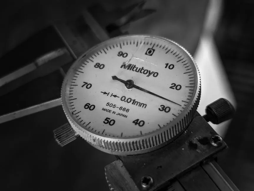
A vision measuring machine captures an image of a part with an industrial camera, locates the edges of features inside that image, and converts the pixel coordinates into real units (mm or µm) by dividing pixel pitch by a calibrated µm/pixel scale factor [S8].
The same camera-plus-lens chain delivers lengths, widths, diameters, hole positions, and angular relationships visible from one viewing direction, which is why a vision measuring machine has become the default non-contact tool for small, flat, or delicate parts [S1][S5].
Pixel-to-Size Conversion: The Core Math
Every VMM measurement starts with a calibration that links image pixels to real-world length using a reference artifact, typically a glass scale or certified stage micrometer; the resulting µm/pixel constant is what the software applies to every edge-to-edge distance it computes [S8]. A 1.5-megapixel camera (1400 × 1050 px) imaging a 21 mm × 28 mm field of view yields roughly 15 µm per pixel, while a 5-megapixel sensor over the same field gives about 8 µm/pixel and is one of the levers engineers use to push VMM accuracy toward 5 µm and below [S3].
Sub-pixel edge detection, where the software fits a grey-level transition to a sub-pixel position rather than snapping to the nearest pixel boundary, is what separates a vision system from a simple pixel counter and is the second accuracy lever; the third is the telecentric lens that holds magnification constant across the working depth [S2][S3].
Telecentric Optics, Depth of Field, and Why the Stage Stops Moving
Field-of-view VMMs pair the camera with a telecentric lens so magnification stays the same whether a feature sits in the center or at the corner of the image, which is what lets the part be placed anywhere in view and still measure correctly [S3]. A traditional optical measuring microscope has a field of view of about 0.5 mm to 20 mm and a depth of field of a few microns to a few millimetres, forcing a moving stage; a wide-field telecentric VMM exposes the whole sample in one frame and lifts depth of focus to 40 mm or more, so a single snapshot replaces stage rastering [S3].
The non-contact nature of the same camera path is also why VMMs are specified for soft or coated components such as O-rings, gaskets, stents, PCB substrates, and thin-film wafers, where a caliper jaw would damage the very surface being inspected [S4][S1].
Lighting, Edge Detection, and the 2D vs 3D Question
Edge detection accuracy collapses without controlled illumination, which is why every modern VMM pairs the camera with selectable light sources: coaxial light for reflective metal, ring light to bring out edge shadow on matte surfaces, transmitted (back) light to project a clean silhouette for diameter and gap checks, and strobe light to freeze a part on a moving line at high speed [S4]. The result is a high-contrast transition that the machine vision system can threshold reliably, then feed into the same µm/pixel scale factor for an angle, radius, or distance [S2].
Object dimension machine vision is commonly split into 1D (single linear distance), 2D (planar lengths, diameters, hole positions visible in one frame), and 3D (full spatial geometry from stereo, laser triangulation, or structured light), with the 2D single-camera case being the highest-volume setup on shop floors because it needs only one camera, one calibrated lens, and no moving probe [S2][S5]. For deeper comparisons of how vision sits against tactile coordinate measuring machines and laser scanning, the geometry dictates the pick: CMMs for internal bores and full GD&T per ISO 10360, vision for 2D features and high throughput, laser for freeform surfaces [S5].
Throughput, Accuracy Envelope, and Where Vision Wins
A single-camera VMM running a simple 2D measurement loop at 60+ frames per second can out-inspect a manual gauge by orders of magnitude, while a skilled operator using a caliper on a 50 mm shaft can still achieve roughly ±0.01 mm accuracy, so the trade-off is always measured uncertainty versus measured rate [S2]. Vision systems also remove inter-operator variation and operator fatigue from the loop, and that is the real reason production lines are converting first-article checks from hand gauges to inline cameras rather than chasing the last 5 µm of CMM-class accuracy [S2][S4].
The same camera frame that carries the dimension can also carry a machine vision ID read for traceability, turning one inspection station into a part-measures-and-logs-itself node on the line [S4].
Selection Criteria: Manual Stage, CNC, and Multi-Sensor Hybrids
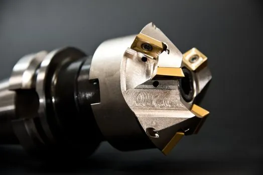
Buyers typically pick from three configurations: manual systems, where the operator drives the stage and focuses the camera on each feature (best for R&D and one-offs); automated CNC VMMs, where the stage, focus, and lighting all run from a program (best for high-volume repetitive inspection); and multi-sensor machines that bolt a tactile probe or laser scanner onto the same frame, so vision handles fast 2D checks and the probe covers the features the camera cannot see [S4][S7].
The cross-platform options, such as the ZEISS Optical Series, sit the vision camera and an optional tactile sensor on one bridge so a single part program can flip from optical to contact without re-fixturing [S7]. A vision controller then sequences the lighting, exposure, edge-detection algorithm, and pass/fail output so the part never leaves the field of view between checks [S2].
Limitations, Failure Modes, and Sourcing the Standard
A single fixed camera cannot see a bore wall, an internal groove, or the bottom face of a blind step; those features still need a tactile probe, a laser line scanner, or a multi-view rig, which is why a 2D vision system is a complement to, not a replacement for, a CMM on GD&T-heavy prints [S5]. Calibration drift, dirty optics, and uncontrolled ambient light are the three failure modes that quietly degrade VMM accuracy long before the camera itself fails, so a documented recalibration schedule against a traceable artifact is part of the spec, not an option [S8][S4].
Vision dimensional work inherits its metrological traceability from CMM-style references: ISO 10360 governs the acceptance and reverification tests for length-measuring systems and is the standard auditors look for when a vision line is replacing a coordinate-measuring-machine gauge in a first-article report [S5].
What a Buyer Should Ask for on a VMM Spec Sheet
Pin these six items on a request for quotation, and you will cover 90% of the integration risk: camera resolution in megapixels, µm/pixel at the working field of view, telecentricity specification (typically less than 0.1° chief-ray angle), depth of field at the chosen magnification, lighting options the price actually includes, and a written repeatability figure on a certified artifact at that same field of view [S3][S4][S8]. Also ask which file formats the embedded part program exports (DXF, IGES, STEP, QIF) so the vision data lands in the same CAD/PLM stack as the rest of the metrology lab [S2].
A reasonable next node is to ask the vendor for a sample report from a part in the same tolerance class as yours, and to confirm whether the proposed contour measuring machine complement is needed for the radii and profile features the camera alone cannot grade. Trackable signals to watch over the next two quarters are the released µm/pixel ratings on new 5-megapixel telecentric VMM stages and any OEM disclosure of AI-assisted sub-pixel edge detection moving the accuracy floor below 5 µm at 20 mm field of view [S2][S8].
See also our earlier report, 2x2 vs 2x4 Suspended Ceiling Tile Cost: A Square-Foot Decision Matrix.