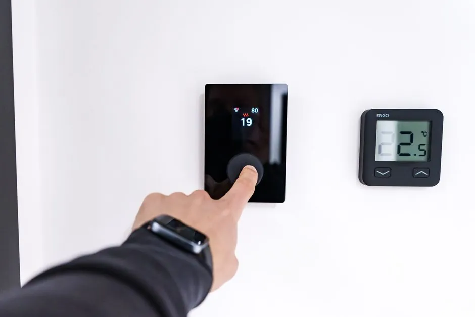
A temperature transmitter conditions a low-level sensor signal (mV from a thermocouple, resistance from an RTD) into a load-independent 4–20 mA or 0–10 V output on a two-wire loop, while a temperature indicator is a local panel- or housing-mounted display that shows the measured value in °C or °F without producing a control-grade output [S4][S5].
The two devices answer different questions: a transmitter answers "what is the process value, and what standardized current should the controller read?", while an indicator answers "what does the value look like to a person standing next to the sensor?". Field-mount transmitters typically integrate an optional local LCD indicator inside a die-cast aluminum or stainless steel housing, so the indicator is a feature of the transmitter, not a separate functional class [S1].
Functional split: signal conditioning vs display
A temperature transmitter linearizes the non-linear sensor curve, filters EMC noise, isolates the sensor ground from the control loop, and scales the result into a 4–20 mA current that survives thousands of feet of cable [S3][S4]. On a standard Pt100 RTD, the raw signal is 100 Ω at 0 °C and 138.5 Ω at 100 °C, a delta of only 38.5 Ω across the full industrial range, which is why on-sensor amplification and linearization are not optional [S4]. A temperature indicator performs no such conditioning; it accepts an already-scaled input (commonly 4–20 mA, 0–10 V, or a thermocouple/RTD signal via an internal digitizer) and drives a numeric readout, so it adds visibility but not control capability.
Mounting tracks function: head-mount transmitters fit inside the thermocouple or RTD connection head on the thermowell, cutting wiring runs and reducing corrosion points; field-mount transmitters live in a separate IP-rated enclosure with the optional LCD visible to operators [S1]. Indicators are commonly supplied as panel meters (96×48 mm, 48×48 mm DIN cuts), loop-powered digital displays powered from the 4–20 mA drop itself, or as a hinged-window LCD inside the transmitter housing. For comparison with adjacent process instruments, see the broader definition in the temperature transmitter reference page, which covers the conditioning role in detail.
Sensor compatibility and signal types
Universal transmitter inputs accept the three dominant industrial sensor families: thermocouples (J, K, T, E, R, S, B, N types; spans from −200 °C up to 1750 °C), RTDs (Pt100, Pt1000, Ni100 with 2-, 3-, or 4-wire hookups), and thermistors or mV/resistance inputs [S3][S6]. ABB's TTH200 head-mount transmitter lists a universal input for both RTD and thermocouple probes with 0.1% accuracy, an unusual spec level for that form factor [S1]. Thermocouples cover the widest span (−200 °C to 1750 °C) and are the cheapest per assembly, but they drift and need compensating cable; Pt100 RTDs cap around 850 °C but give the best stability, with 5–6 °C of error for every 1–2 Ω of uncompensated lead resistance on a two-wire hookup, which is why three-wire RTDs are the default in process plants [S3][S4].
Indicators accept either a sensor input directly (low-cost local thermometers with built-in RTD) or a transmitter-style 4–20 mA / 0–10 V input (panel meters that scale an analog value to engineering units). A loop-powered 4–20 mA indicator drops typically 3–6 V across its shunt and display, which must be budgeted against the 24 V DC loop supply. For a side-by-side of how loop-powered displays compare to powered ones, the level transmitter page covers the same two-wire loop power-budget trade-off in liquid measurement.
Selection criteria: when to spec which
Spec a temperature transmitter when the measured value must (a) reach a DCS, PLC, or SCADA node, (b) drive a control loop or safety interlock, (c) traverse more than a few metres of cable, or (d) be linearized, isolated, or cold-junction-compensated at the point of measurement [S3][S5]. Two-wire 4–20 mA loops are the universal default because the same pair carries power to the transmitter and the analog output back to the controller, and the 4–20 mA current is load-independent, so a 1 km run of shielded twisted pair looks the same electrically as a 10 m jump [S1][S3].
Spec a temperature indicator when the requirement is purely local visibility: a gauge on a skid, a redundant readout next to a transmitter, an oven door display, or a stand-alone freeze-protection monitor. Indicators cost less than full transmitters, need no loop power budget, and avoid the configuration overhead of HART or Foundation Fieldbus commissioning. They are the wrong choice when the value must be trended, alarmed remotely, or used for closed-loop control, because most indicators offer only relay contacts (for alarm trips) and no proportional control output.
Comparison: transmitter vs indicator on decision criteria
On four decision criteria the split is clear. Output: transmitter produces 4–20 mA, 0–10 V, HART, or fieldbus digital; indicator produces a local numeric display (and optionally 1–2 alarm relays). Signal conditioning: transmitter linearizes, isolates, filters, and cold-junction-compensates; indicator passes the signal through to a digitizer or ADC without isolation. Cabling and distance: transmitter survives km-scale runs on twisted pair; indicator is point-of-measurement only. Role in the loop: transmitter feeds control and logging; indicator feeds operators [S3][S4][S5]. A useful structural analogy in adjacent instrumentation is the split between a pressure transmitter (loop-powered, control-grade) and a local bourdon-tube gauge (mechanical readout, no control output).
Failure modes and common pitfalls
Transmitter pitfalls: configuring the wrong sensor type burns the input (e.g. setting a thermocouple input as RTD and feeding in 138 Ω of resistance); missing cold-junction compensation on a thermocouple input adds ambient-temperature error; sharing a 4–20 mA loop with a non-isolated indicator steals 3–6 V of loop budget and can push marginal 12 V systems out of range [S3][S6]. Indicator pitfalls: mis-scaling the input range (4 mA = 0 °C vs 4 mA = −17.7 °C) gives an offset error visible only on the panel; loop-powered indicators with high voltage drop starve the transmitter when both are on the same 24 V loop [S3].
Sensor-level pitfalls apply to both: a two-wire RTD on a long run introduces 5–6 °C error per 1–2 Ω of lead resistance, which neither a transmitter nor an indicator can fix in software without a three- or four-wire hookup [S4]. Thermistors, while cheap and fast, are nonlinear and require lookup tables the indicator or transmitter must hold, which is why they are usually restricted to motor-winding and compressor-discharge protection rather than process control [S4].
Standards, sourcing, and integration notes
Transmitter compliance commonly includes IEC 60079 series for explosion-protected enclosures (ATEX category 2/3 zones in Europe), IECEx for international hazardous-area acceptance, and NAMUR NE 43 for the 4–20 mA fault-current band (3.6 mA / 21 mA) [S1]. HART 7 overlays the 4–20 mA analog signal with a 1200/2200 Hz FSK keying, so the same two wires carry both the analog value for legacy controllers and a digital channel for configuration and diagnostics. The TTH200 from ABB lists 0.1% of span accuracy and multiple compliances for explosion protection and extended diagnostics in its published spec sheet, which is the order of magnitude engineers should expect from a current-generation head-mount device [S1].
For an in-process look at how loop-powered instruments behave on the same two wires, the differential pressure transmitter page runs through the same voltage-drop budget for a flow-or-level service. Process plants that already spec dial indicators for mechanical gauge boards typically add electronic temperature transmitters only where the value must enter the control system, keeping local dial gauges and panel indicators for operator visibility at the skid.
Bottom line for a control engineer: buy a temperature transmitter when the value must leave the thermowell head; buy a temperature indicator when the value only has to reach the operator's eyes. Mixing the two is normal: a head-mount transmitter with an optional LCD is the most common field configuration, and a loop-powered indicator downstream of a transmitter is the most common panel-mount configuration. To verify a specific build against site standards, pull the certificate numbers (ATEX, IECEx, SIL) from the manufacturer's datasheet and cross-check that the sensor type code matches the field wiring, not the purchase-order line.
See also our earlier report, 2x2 vs 2x4 Suspended Ceiling Tile Cost: A Square-Foot Decision Matrix.