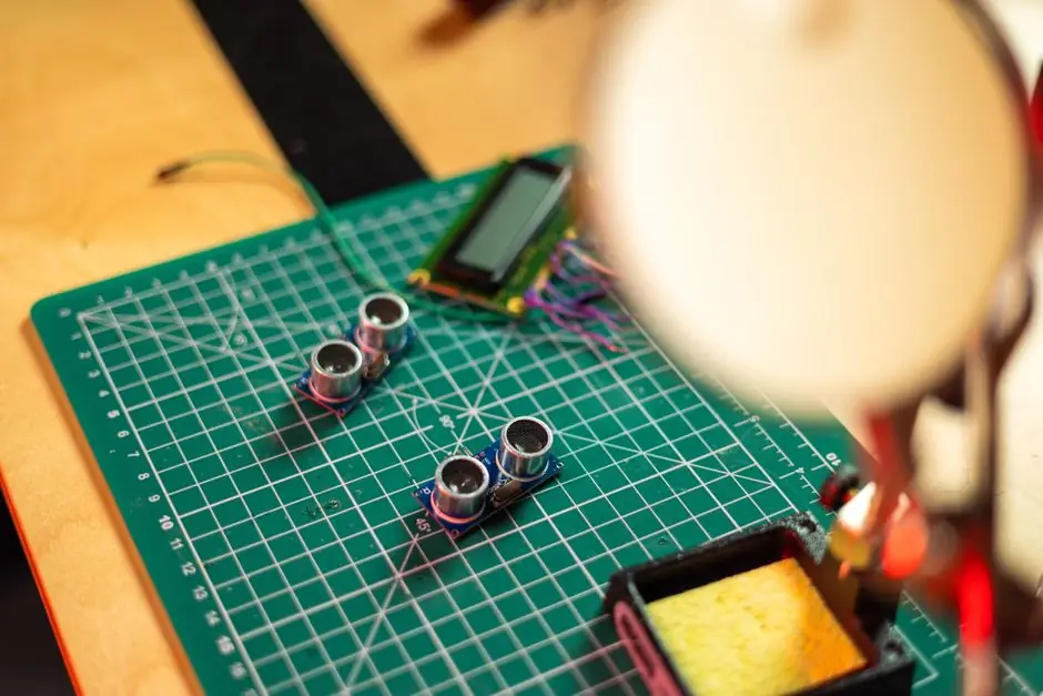
Inductive proximity sensors are the default pick for non-contact detection of conductive metal, with catalogue sensing distances typically 1 mm to 15 mm for standard-range (LR) bodies and 2 mm to 25 mm for long-range (FR) bodies [S5].
The decision tree has four hard gates, target material, operating gap, housing, and output, and every later choice collapses if the first gate fails; this article lays out each gate with the numeric thresholds a buyer needs to spec a part on the first pass [S1][S2][S5].
What an Inductive Sensor Actually Is, and When to Walk Away
An inductive proximity sensor has four functional blocks: a coil, an oscillator, a detection circuit, and an output circuit, with the coil generating a high-frequency electromagnetic field and eddy currents in the target loading the oscillator once conductive metal enters the field [S5][S7]. Typical targets are ordinary steel, stainless steel, aluminum, brass, and copper, and any metal gear, slide, bracket, or end-stop fits the use case [S5].
Inductive sensors detect metallic objects, so they cannot be used when the target is non-metallic, because the operating principle needs a conductive target; capacitive sensors are used for all other materials [S3]. Magnetic proximity sensors are the right pick only when the moving part already carries a permanent magnet, such as a pneumatic-cylinder piston, because a plain steel clamp without a magnet will not switch a magnetic sensor reliably [S5].
The Four-Step Selection Workflow
Define application requirements first: target material and geometry, required sensing distance, supply voltage, output type, switching frequency, mounting space, and environment, because each later parameter has no meaning until the previous one is fixed [S8]. The fastest working rule, used as a tie-breaker at the end, is: choose inductive for ordinary steel, stainless steel, aluminum, brass, copper, and other conductive metals [S5].
A long-standing sizing rule from the controls vendor community is that the target should be at least three times the size of the sensing face of the sensor you select, to keep the published operating distance valid and avoid edge-effect dropouts [S1]. Sensing distance is the gap between the sensor tip and the object, and the published number is normally calculated against FE360 mild steel, so non-ferrous targets like aluminum or stainless steel require a derate and sometimes a shorter nominal range or a correction factor in the catalogue [S3].
Sensing Distance, Extended Range, and the Target-Material Correction

Step 1 in any selection is the required sensing distance, and the practical split between standard, extended, and triple-range bodies sets the operating gap a buyer can actually rely on [S3]. Extended sensing-distance inductive bodies are commonly offered in 8 mm to 30 mm diameters, and triple-distance bodies in 8 mm and 12 mm formats, with the longer range bought at the cost of a larger face and stricter target-size rules [S3].
Greater operating distance also lets the sensor sit farther from a hot target, which lowers thermal stress and extends service life; in tight machines where the sensor cannot be mounted near the target, longer range is a hard requirement, not a luxury [S3]. For non-ferrous targets such as aluminum or copper, expect a published range reduction; some vendors offer stainless-steel-rated sensing technology that measures virtually all metals at the catalogue distance, which is the cleanest way to keep a single range number across mixed SKUs on a line [S3].
Shielded vs Unshielded, and the Mounting Geometry Trade
Step 2 is mounting space, and step 3 is shielded (embeddable) versus unshielded (non-embeddable) construction; the rule is that unshielded bodies allow longer sensing distances, while shielded bodies allow flush mounting in metal because their electromagnetic field is shaped to tolerate surrounding metal [S3]. A rectangular housing with the same internal electronics is available when a round or short-body standard part will not physically fit, useful for slide-position or tool-clamp verification on machine tools [S3].
The trade is concrete: a flush-mount M12 shielded sensor has a tighter sensing face and a shorter rated range than a non-flush M12 of the same family, so the choice is range-versus-mechanical-fit, and the decision must be made before output type is even discussed [S3]. On inductive sensor pages, the rated sn (nominal) and sa (assured) distances are listed separately, and a robust design targets an installed gap at roughly 0.81 × sn so that manufacturing tolerances and temperature drift do not push the sensor past the switch point.
Environment, IP Rating, and Temperature
Step 4 is the environment, and the questions are the same ones on every spec sheet: underwater, high-temperature, oil splash, welding spatter, coolants, cleaning agents, and EMC exposure, because each one rules out a body material, a sealing class, or a cable jacket [S3][S6]. Common industrial bodies carry IP67 as a baseline, with IP68 or IP69K specified for food-and-beverable washdown or outdoor installations; stainless-steel housings (1.4404 / 316L) are the standard answer for chemical exposure and hygienic zones [S6].
Humidity, dust, and vibration resistance are the headline advantages of inductive over magnetic and over mechanical limit switches in harsh industrial settings [S4].
Electrical Interface: NPN, PNP, 2-Wire, and IO-Link
The output side of an inductive sensor runs from simple binary NPN or PNP transistors at 10-30 V DC, through DC 2-wire (suitable for NAMUR or low-leakage PLC inputs) and AC 2-wire, up to IO-Link for digital diagnostics [S5]. Magnetic sensors add Hall-effect NPN/PNP and reed-based AC/DC two-wire options, but inductive parts stick to the NPN, PNP, DC 2-wire, and selected AC 2-wire families, with IO-Link increasingly standard on new European builds [S5].
Switching frequency is a separate axis and is the deciding factor for high-speed counting or small-part detection on a fast conveyor: standard inductive bodies switch at 1-3 kHz, while high-speed parts reach 5-10 kHz, and that number must be checked against the input filter of the PLC or counter module. For position feedback on hydraulic or pneumatic cylinders, the comparison with magnetic sensor options is a parallel track, with magnetic dominant when the piston already carries a magnet and inductive dominant when it does not [S5].
Criteria-Based Comparison of the Main Form Factors
Use this short table to line up the realistic options against four decision criteria, range, mounting, environment, and output, before pulling a datasheet: [S7]
Cylindrical standard-range LR (M8, M12, M18, M30): typical 1-15 mm range, shielded or unshielded, IP67 stainless or nickel-plated brass, NPN/PNP/2-wire; the default pick for general factory automation [S5].
Cylindrical long-range FR (same diameters): 2-25 mm range, larger face and shorter target-size factor, NPN/PNP/2-wire; pick when the sensor must sit back from the target due to temperature, overshoot, or mechanical clearance [S3][S5].
Rectangular/block body: same internal electronics, smaller footprint for tight slides or tool-clamp verification, available in PNP/NPN and IO-Link; pick when a round body will not fit the machine [S3].
Stainless-steel hygienic or high-temperature body: 1.4404 / 316L housing, IP67-IP69K, rated up to +120 °C or higher with remote amplifier; pick for washdown food lines, chemical plants, and foundry cells [S3][S6].
For sub-mm precision in metrology, an LVDT sensor is the correct tool, not an inductive proximity switch, because LVDTs are analog contacting transducers for displacement, while inductive proximity sensors are binary presence detectors.
Who Should Not Pick the Mainstream Inductive Option
Do not pick a standard inductive sensor when the target is non-metallic (plastic pellets, liquid level, paper, glass), because the operating principle needs conductive metal; the right tool is a capacitive sensor, which detects changes in the electrical field and can be tuned to ignore or to see a specific dielectric [S4]. Do not pick inductive when the target sits behind a metal barrier, because the first conductive layer becomes the target and either masks the real object or causes permanent oscillation, a failure mode that is not fixable by re-rating the range [S5].
Do not pick a magnetic sensor when the target is plain steel without a magnet, the failure mode is a phantom install: the wiring checks out, the bracket is rigid, the PLC input is normal, and the signal still drops in and out, because the sensor family is wrong for the target [S5]. For non-contact position over a longer stroke, compare against displacement sensor technologies, which deliver an analog position value rather than a binary trigger.
Selection Checklist Before Issuing the PO
Confirm four things on the datasheet before ordering: target material and size (the 3× face rule, the FE360 reference, and any derate for stainless or aluminum) [S1][S3]; rated sn and sa, and that the installed gap sits at 0.81 × sn for tolerance headroom; IP rating and temperature range matched to the worst-case environment, including cleaning chemistry and washdown temperature [S6]; and output type, switching frequency, and connector (M8, M12, cable exit) matched to the PLC card or flow sensor cabinet wiring practice. For OEMs building private 5G or IIoT-ready cells, see the Industrial 5G Module Landscape 2026 for the network side of that same cabinet. For foundries and die-cast cells where inductive sensors sit near hot dies, the failure modes covered in the Hot Chamber Die Casting Machine Failure Modes and Prevention field guide map directly onto the temperature and spatter derating above.