An SVG is sized first by the trigonometric formula Qc = P × (tan φ1 − tan φ2), then rounded up to the nearest modular step, with 100 kVAr being the most common cabinet increment and wall-mount modules parallelable in pairs to expand capacity [S1][S3].
The decision to choose an IGBT-based SVG over a traditional stepped capacitor bank is driven by load dynamics: SVGs respond in under 10 ms and provide stepless, bidirectional (inductive and capacitive) compensation, while capacitor banks only switch in fixed steps and can lag a fluctuating load [S2][S4].
How an SVG Replaces or Supplements a Capacitor Bank
An SVG is a power-electronic device, usually an IGBT-based voltage-source inverter, that senses load current through external current transformers, calculates the reactive component, and injects a leading or lagging current to drive the power factor toward the target without mechanical or contactor switching [S4][S6]. Continuous compensation, not stepwise insertion, is the core functional difference from a conventional bank, and the controller is bidirectional, so it can absorb capacitive vars as easily as it supplies inductive ones, a behaviour a plain capacitor bank cannot emulate without reactors [S4].
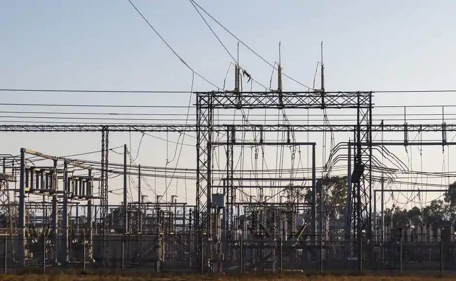
Where an SVG sits in a substation or on a feeder, the function is the same as the static var compensator (SVC) it is often compared with: regulate voltage and reactive power at the point of common coupling. The architectural difference is that an SVC uses thyristor-controlled reactors (TCR) with thyristor-switched capacitor (TSC) banks, while an SVG is a self-commutated inverter, which is why response time and low-voltage behaviour diverge between the two [S4]. Reference designs in the 33 kV class show optimized placement raising bus voltage from 94.69% to 97.90% of nominal, evidence that location, not just rating, drives the outcome of any var-compensation project [S5].
Sizing Math: From Electricity Bill to kVAr
The accurate sizing path is the trigonometric formula Qc = P × (tan φ1 − tan φ2), where P is the maximum measured active power in kW, φ1 is the original (pre-compensation) power factor angle, and φ2 is the target angle [S3]. Worked example: 800 kW load at cos φ1 = 0.75, target cos φ2 = 0.95, gives tan φ1 ≈ 0.882 and tan φ2 ≈ 0.329, so Qc ≈ 800 × 0.553 ≈ 442 kVAr; the cabinet must then be rounded up to the next 100 kVAr module, here 500 kVAr [S3]. A second worked example from the Strong Power guide uses a 1000 kW load taken from 0.75 to 0.98, yielding 882 − 203 = 679 kVAr, rounded up to a 700 kVAr cabinet [S1]. Both examples illustrate the same rule: round to the next available module size, never round down, because an undersized SVG running at full load will not reach the utility target.
The minimum data set a sizing engineer should collect before running that formula is shown in the CNBYG parameter table: transformer kVA, actual active power P in kW, original power factor cos φ1, target power factor cos φ2, and total harmonic current distortion THDi as a percentage, all measured at the main load side with a power quality analyzer or read from the multifunction meter and the electricity bill [S3]. For a design-stage site where no measurement exists, the same variables can be estimated through load-listing tools such as PowerCad and then validated once the plant is energised [S1]. Target power factor is normally set between 0.95 and 0.99 to satisfy utility tariff rules while leaving a small margin against the leading-power-factor penalty many utilities apply above cos φ = 1.0 [S3].
3-Wire vs 4-Wire, Cabinet Expansion, and IP Rating
SVG topology choice is driven by network balance, not by kVAr. A 3-wire SVG is specified for balanced networks typical of mining, heavy industrial, food and beverage, and general manufacturing; a 4-wire SVG with a fully rated neutral is required where single-phase or unbalanced loads create a neutral current, the case in commercial buildings, offices, education campuses, and shopping centres [S1]. The 4-wire option is the more expensive variant and should not be ordered unless a power quality audit or meter data confirms a neutral imbalance issue.
Capacity expansion is handled at the cabinet level rather than by oversizing one unit. The Strong Power guide lists cabinet sizes in 100 kVAr modular steps, and wall-mount SVGs can be doubled by paralleling two systems, so a 700 kVAr requirement can be built from one 400 kVAr and one 300 kVAr cabinet or from seven 100 kVAr modules rather than a single 700 kVAr unit [S1]. SinaVa's product specification states the same modular logic, parallelable SVG units, and adds that the response time of the assembled system stays under 10 ms regardless of how many modules are stacked [S4]. Spare capacity should be budgeted at the sizing step if the plant is expected to add drives, welders, or extra production lines within the next 3 to 5 years, because adding a second cabinet later is cheaper than running the first one chronically at full load.
When to Pick SVG vs Capacitor Bank vs Harmonic Filter
Capacitor banks remain the right answer when the load is stable, the harmonic environment is controlled, and the budget is dominated by €/kVAr rather than by kVAr/ms. They switch in fixed steps, are straightforward to install, and have decades of field data behind them, which is why they are still the most widely used correction method in plants without drives, large UPSs, or arc furnaces [S2]. They fail, however, the moment the load becomes impulsive: each step insertion takes hundreds of milliseconds, contactor-switched banks cause transients on every transition, and there is no way to absorb leading vars if the network goes capacitive.
SVG is the right answer when reactive power demand varies in less than a second, when leading (capacitive) compensation is ever required, or when a stepped bank would be hunting constantly. The SinaVa reference load list, welding machines, cranes, compressors, rolling mills, elevators, data centres, and renewable inverters, all share a fast, bidirectional var profile that a stepped bank cannot track [S4]. One vendor comparison table puts SVG response in the millisecond band, SVC (thyristor) as fast but coarser, and switched capacitors as the slowest of the three, and adds that SVG maintains compensation at reduced voltage better than the SVC, because the self-commutated inverter synthesises reactive current rather than relying on capacitor reactive output that scales with V² [S4].
For plants dominated by variable-frequency drives, an SVG and a harmonic filter are complementary, not interchangeable: the SVG cleans the power factor, while the passive or active filter absorbs the harmonic current the drives inject. The 4-quadrant capability of the IGBT inverter also lets a modern SVG trim residual harmonics slightly, but it should not be sold as a harmonic-mitigation device on its own, and the sizing sheet must record THDi in percent before the rating is fixed [S3].
Use Cases: Mining, Data Centers, Renewables, and Welding Lines

Mining sites are the textbook SVG application: long feeder cables, large crusher and conveyor drives, and weak utility connections where voltage support matters as much as power factor. The 3-wire topology is correct for the upstream network, and the cabinet typically needs a high IP rating because of dust. Readers comparing vendor offers against a duty profile will find the practical static var generator selection map for mining useful for cross-checking the kVAr and IP decisions below the formula. [S1]
Data centres and inverter-heavy renewable plants need the 4-wire variant only if single-phase IT loads create a neutral current; otherwise 3-wire suffices, and the SVG sits upstream of the UPS to keep the utility-side power factor inside the tariff window. Welding lines, rolling mills, and elevator banks sit downstream of the main switchboard, with a 4-wire SVG where phase imbalance is documented and 3-wire otherwise, and the cabinet should be sized with the maximum concurrent load, not the nameplate sum, because not all welders or elevators run at once. For sites that combine an SVG with a back-up generator, the industrial generator sizing guide covers the active-power side of the same project so the var and Watt ratings stay consistent.
Limitations, Failure Modes, and What the Spec Sheet Will Not Tell You
An SVG cannot fix an upstream problem: if the transformer is overloaded or the cable is undersized, improving the power factor only reduces the current drawn for the same kW, it does not raise the transformer rating. Low power factor at the meter is also a lagging-only symptom in most industrial sites, but a fully loaded SVG with rooftop solar or a long capacitive cable run can push the network leading, and the same inverter that supplies vars must then absorb them, which is why the bidirectional specification is a real operating requirement, not a marketing line [S4][S7].
CT placement is the most common field failure source. The SVG must see the total load current, not just one feeder, and the polarity must be correct, otherwise the controller inverts the compensation command and the power factor worsens instead of improving. The SinaVa description of the four-step operating sequence (current detection, reactive calculation, current generation, grid compensation) makes clear that the first step is a hardware step, not a software one, and the Strong Power guide includes a separate breaker, cable, and CT selection table for that reason [S1][S4]. Finally, an SVG loses effectiveness in a deep voltage sag, because the inverter needs bus voltage to keep commutating, and a hybrid installation with a traditional capacitor bank on a contactor can hold the network through the sag while the SVG recovers, which is the standard architecture in many mining and data-centre specifications.
Trackable signals for the next planning cycle: monitor monthly electricity bills for the reactive-power penalty line (or the displacement power factor the utility bills against), log the SVG operating kVAr against measured P and cos φ, and re-measure THDi after every major load change, because drives added to the plant push both the var and the harmonic profile in the same direction and the SVG must be re-sized, not merely re-tuned, when they do.
For the relevant spec sheets and selection criteria, see static var generator, linear guide, and crossed roller guide.