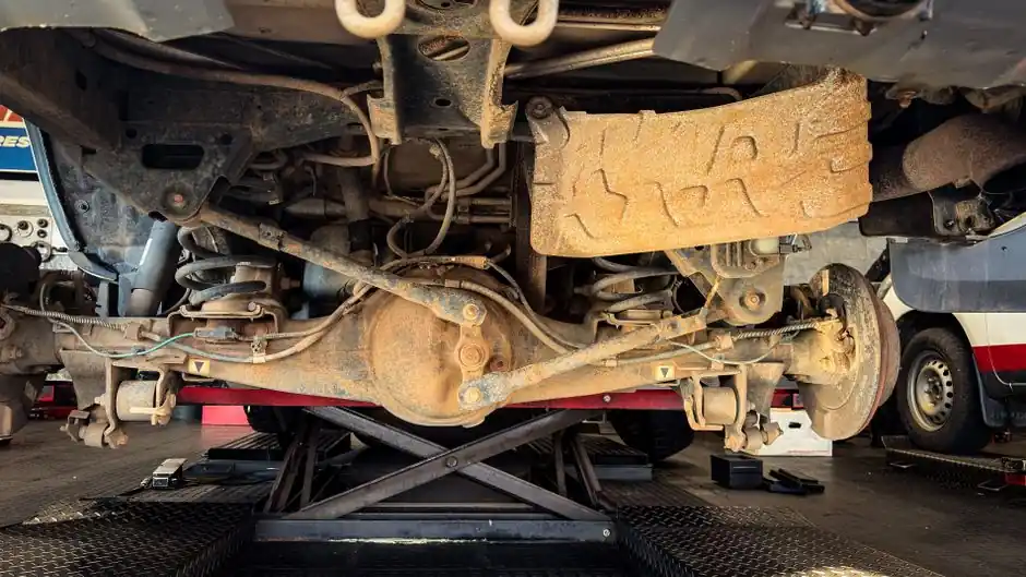
Most premature hydraulic actuator failures I see on commissioning day trace back to two root causes: side load from a misaligned linkage, and proof pressure that was never confirmed against a 1.5x to 2x MOP margin [S9]. Get those right and the rest of the acceptance walk becomes routine.
This guide is for field engineers and commissioning leads sizing and installing linear and scotch-yoke hydraulic actuators on valve, subsea, and heavy-machinery service, where thrust typically runs 50–500 kN at 200–350 bar supply [S5]. It treats the actuator as part of a hydraulic system, not as a standalone part, because installation is the moment the cylinder, the linkage, and the HPU/accumulator get bound into one force loop.
Pre-Installation: Nameplate, Damage Check, and Hydraulic Circuit Readiness
Before lifting the actuator onto its bracket, the assembly must be inspected for shipping damage and any damaged part must be replaced with original spares, not "equivalent" substitutes; the nameplate has to be verified against the work order, with focus on rated pressure, stroke, and the double-acting vs spring-return action [S1]. Hydronic oil viscosity, cleanliness (ISO 4406 target), and reservoir level on the HPU should be confirmed before any hose is pressurised, because a starved pump during the first stroke is the single most common cause of jerky motion I troubleshoot on new builds [S3].
For double-acting linear units, retract and extend areas differ, so a single nameplate pressure reading does not guarantee identical force in both directions; document both areas and the MOP, then plan the proof-pressure test at 1.5x to 2x MOP per the metallurgical and pressure-resistance standards the actuator was designed to [S9]. On subsea or offshore work rated to API 6A ANSI 2000–20,000 WP, this check is not optional, because the actuator will spend its life at a stress level where a single under-rated hose or fitting decides the next shutdown [S5].
Mounting, Orientation, and Pivot Alignment to Kill Side Load
Alignment is where most field hours are lost and most seals are ruined. The actuator should provide push and pull, while the machine structure provides guidance: pivots must stay in the same plane as the linkage through the full stroke, and the rod end has to rotate freely at both mounts so it can self-align as the geometry changes during travel [S3]. If you can feel the rod binding by hand at mid-stroke, you will see stick-slip, slower retract, and a stop point that drifts with approach direction once the system is live.
Pre-rotation rules from the Econ Fig. 21401 manual require the actuator orientation to match the nameplate drawing before any rod-end hardware is torqued, because re-orienting after the clevis is already pinned is what bends the rod [S1]. On scotch-yoke quarter-turn units, the yoke slot must sit centred on the valve stem key at the 0° and 90° positions, and the mechanical end-stops must take the load, not the actuator piston slamming into its cylinder cap, or the cushion becomes a wear part rather than a safety feature [S7].
Hydraulic Supply, HPU Sizing, and Accumulator Sizing

For large-bore valve and ESD service, the hydraulic supply sits in the 200–350 bar window, with a typical maximum of 350 bar for scotch-yoke and linear thrust packages, and a thrust envelope that reaches 500 kN on the largest linear units [S5]. Compare that to the 4–8 bar typical of pneumatic systems, and you see why hydraulic becomes the only practical choice above ~10,000 Nm torque or ~50 kN linear thrust, or on pipeline valves above 18" and Class 900 service [S5].
ESD and subsea systems add one more dimension: a hydraulic accumulator sized for 3–5 emergency close operations after the HPU loses supply pressure, so the spring-return fail-close path can actually run to completion when station power is the trigger event [S5]. For a deeper look at how cylinder bore, rod diameter, and stroke drive the pump and accumulator numbers, the hydraulic cylinder reference is the right companion; for the rotary output side, a hydraulic motor overview explains the torque/speed trade-offs when the actuator is driving a continuous-rotation load rather than a valve stem. For a wider vendor and spec view across linear, scotch-yoke, and rack-and-pinion units, the Hydraulic Actuator Types, Spec Ranges, and Selection Map article lines up the same force classes against typical lead times.
Commissioning Sequence: Stroke, Pressure, and Cycle Acceptance
First-energise rules are explicit in the actuator manuals: do not apply hydraulic pressure until the linkage or valve assembly is installed, and never install insulation on any part of the actuator housing, because trapped heat under insulation is a documented cause of seal failure and premature stroke-end drift [S4]. Once lines are connected, bleed air from both cylinder ports at the highest practical point, then move the system slowly to each end of stroke to confirm there is no hard contact that spikes load, and to verify the mechanical stops, not the piston, absorb the end-of-travel energy [S3].
A representative small-frame linear unit (DC HOUSE 12 V, 300 W hydraulic motor, 0.3 cc/r pump, 200 mm stroke, 390 mm retracted length) reaches 8000 N push at a free-load speed of 13 mm/s, which is a useful sanity check when a much larger industrial actuator behaves an order of magnitude off the predicted speed on first stroke [S6]. For rotary units, the eight-point commissioning checklist from senior field engineers adds: confirm the base flats are turned only with the specified 1-5/8" open-ended wrench, never by twisting the actuator housing, and re-check bolt torque on the mounting flange after the first 10 full cycles, because gasket compression on a new flange can settle unevenly [S4][S7].
Safety, Standards, and When to Stop and Escalate
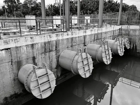
Pressure-boundary and load-bearing components should follow established metallurgy rules: ASTM A108 or AISI 4140 for shafts and rods, 316L or 17-4PH stainless where corrosion or subsea exposure is in scope, and a maximum operating pressure backed by a proof pressure at 1.5x to 2x MOP, with the actual multiple documented on the test certificate [S9]. Third-party certification through TÜV, UL, CSA, or CE is standard for oil-and-gas and process-valve actuators, and API 6A plus API 6D remain the dominant compliance references for wellhead, valve, and pipeline service [S5][S8].
Escalation triggers I watch for during commissioning: any pressure decay on a 10-minute hold test above 5% of MOP, any visible rod scoring under the first wiper seal, any stroke-end drift greater than 1–2 mm after the spring-return cycle, or any cycle time outside +/-10% of the design number once the system is at operating temperature. If any of these trip, do not run the unit into production duty, because the same symptom on a hydraulic actuator under load tends to walk straight through seals, into the cushion, and out the rod gland within a few hundred cycles. For related electric-side work, the electric actuator installation walkthrough covers torque values and wiring acceptance for the linear and quarter-turn electric units you will see sitting next to these hydraulic ones on the same valve manifold.
Track these two signals after start-up: the HPU reservoir temperature trend across the first 50 hours, and the accumulator pre-charge pressure against the spec sheet on a weekly walk-down. A drifting reservoir temperature usually points to a set-point or cooler problem; a slow loss of pre-charge is a nitrogen-side issue that, left alone, will silently downgrade your ESD close count from the designed 3–5 operations to one, which is the difference between a safe shutdown and a near-miss on the next loss-of-power event [S5][S9].