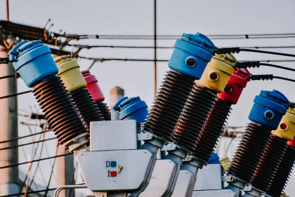
An electric actuator installation is a four-stage job, mechanical mounting, electrical termination, calibration, and functional testing, and the work fits inside a 30–45 minute window for a factory-wired unit or a field replacement [S1][S2].
Most field failures trace back to skipped isolation, missing torque on the bonnet U-bracket, or a 24 V supply that drifts under load; the steps below lock down each one with a verifiable check. A 4 mm hex wrench (or 10 mm wrench), a flat-blade or Phillips screwdriver, and a calibrated torque wrench are the minimum tool kit for both proportional and on-off units [S1][S2].
Pre-installation isolation and mechanical prerequisites
Before the bonnet U-bracket is opened, the upstream and downstream shut-off valves must be closed (upstream first, then downstream) and the pump switched off, so the differential pressure across the valve drops to zero [S1]. The same isolation rule applies to on-off quarter-turn actuators, where ISO 5211 direct mounting is used: the actuator may be oriented in any position, but enough clearance must remain for manual override and future maintenance access [S3]. Storage and pre-power rules also matter: an unpowered actuator stored outdoors or in a humid space must be energised immediately to drive the internal anti-condensation heater, otherwise condensate will pool inside the housing [S3]. A site survey should record ambient temperature, enclosure rating, and media temperature, because the actuator's published operating envelope is the binding constraint, not the valve's [S3].
Tools, fasteners, and torque values that bind the install
For the Siemens SAV proportional actuator on a 4- to 8-inch flanged pressure-independent control valve (40–43 mm standard stroke), the published U-bracket torque is 5 Nm, or 44 in-lbs, using the 10 mm wrench or 4 mm hex [S1]. For the Valworx 5618 on-off quarter-turn series, the rugged aluminium housing is rated Type 4X and IP67 weatherproof; the unit is NOT listed for explosion-proof or hazardous locations, which sets a hard boundary on where this specific actuator can be specified [S3]. The 5618 carries a 70% duty cycle rating, an internal thermal overload with automatic reset, and a thermostatically controlled 4 W anti-condensation heater, all of which constrain how the wiring and duty schedule must be designed [S3]. Conformance to UL Std 429, certification to CSA Std C22.2 No. 139, and EN 60204-1:2006 are the compliance anchors printed on the unit's nameplate [S3].
Mounting sequence: quarter-turn on-off vs proportional linear
Quarter-turn on-off actuators mount directly to the valve using the standard ISO 5211 pad, are orientation-independent, and ship with the mechanical stops pre-set at the factory; no field adjustment of the stops is required [S3]. Proportional linear actuators follow a stricter 8-step sequence: confirm the stem connection plate is in OPEN, open the bonnet U-bracket, pull the stem to full extension, slide the actuator over the bonnet, close the U-bracket, torque to 5 Nm, then rotate the manual adjuster clockwise until the shaft covers the valve-stem head, and finally close the stem connection plate [S1]. A critical caution: once the actuator and valve stem are connected, the actuator must not be rotated on the valve, because rotation will inadvertently adjust the flow setting of the pressure-independent control valve [S1]. The polished valve-stem surface must not be scratched or damaged during handling, since the stem seal relies on that finish [S1].
Wiring, calibration, and signal mapping
The SAV proportional unit requires a 24 Vdc or 24 Vac, Class 2 supply signal to drive a 4- to 8-inch flanged pressure-independent control valve; the wiring-compartment cover is removed with a flat-blade or Phillips screwdriver, and knockouts are provided on the housing for conduit entry [S1]. A position indicator, status indicator, and a manual adjuster with slide switch sit on the housing cover, so the wiring routing should be planned so the cover can be removed without de-energising the unit [S1]. The 5618 on-off actuator is wired with power removed, then energised in the open or closed position to drive the 4 W anti-condensation heater; two auxiliary limit switches are provided for open and closed position confirmation and may be used or left spare [S3]. Calibration on proportional units means mapping the control signal to stroke, then verifying with the local position indicator, while on-off units are functionally tested by stroking the valve electrically and reading the yellow visual position indicator on top of the housing [S1][S3]. For more on how motion components like linear guides and crossed roller guides feed into the upstream machine design, the actuator is only one of several decisions a panel builder makes. When the actuator drives a quarter-turn ball or plug valve, the upstream electric ball valve spec usually dictates the supply voltage and torque class, so the actuator selection has to start there.
Functional testing, cycling, and when to reject the install
Commissioning begins with a manual override check: REMOVE ALL ELECTRICAL POWER to the actuator first, then open the manual override protective cover, insert the supplied hex wrench, and rotate counter-clockwise to open or clockwise to close as required [S3]. The actuator should be cycled at least once per month to keep the gear train and seals mobile, and the housing may be cleaned with warm soapy water only, never solvents, and never pressure-washed [S3]. An installation should be rejected and the actuator pulled out if the polished valve-stem surface is scored, if the U-bracket will not hold 5 Nm without movement, if the enclosure rating does not match the area classification (the 5618 series must not be used in explosion-proof or hazardous applications), or if the thermal overload trips on the first stroke, which signals a binding valve or undersized actuator [S1][S3]. The wider category reference at electric actuator covers sizing and torque-class selection, while spec-driven procurement, the kind of structured comparison an EPC or panel shop runs across vendors, is laid out in the spec-first approach used for sourcing smart meters from China and applies equally to actuator vendor lists.
Limitations, failure modes, and escalation triggers
The published 30-minute expected installation time applies to a factory-installed actuator; a field replacement runs 45 minutes because the existing wiring has to be re-terminated and the valve must be re-isolated [S1]. SAV actuators are limited to hot or chilled water installations, and any use on steam, glycol concentrations above OEM guidance, or potable-water systems with dissimilar-metal concerns is out of scope [S1]. The 5618's 70% duty cycle means continuous modulation above roughly 16.8 hours per day will trip the thermal overload; applications such as rapid cycling of a swing check valve in a pump-discharge line, or any service where the actuator is asked to hold position against a sustained differential, will need a continuous-duty model instead [S3]. When the failure is binding in the gear train or burnt windings, repair is not economical: replace the actuator as a unit, log the torque reading at the time of failure, and escalate to the valve supplier if the binding repeats on a replacement, since the root cause is almost always the valve, not the actuator. An electric pallet truck drivetrain and a process-valve actuator share little mechanically, but both follow the same "spec the duty cycle, then spec the supply" rule that makes a 70% rating a hard ceiling, not a guideline.
Track these signals over the next quarter: OEM release of an updated SAV IOM (Document 129-571) with revised torque values or stroke ranges, any new hazardous-location listing replacing the 5618's "do not use in hazardous applications" constraint, and a published revision of UL Std 429 or CSA C22.2 No. 139 that touches on-off electric actuator construction rules. A reviewer cross-checking the swing check valve spec map against actuator sizing data will see the same torque-vs-ΔP boundary appearing on both sides of the valve-actuator interface.