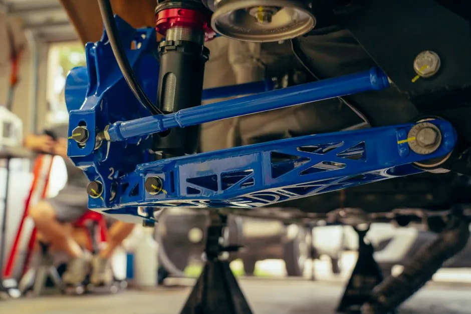
Cement plants concentrate some of the harshest vibration and impact duty in any heavy industry: crusher hammers, rotary feeders, bucket elevators, cooler pushers, and travelling screens all impose impulsive loads that directly shorten bearing and structural life when left un-damped. Hydraulic self-compensating industrial shock absorbers convert impact kinetic energy to heat via metered oil flow through multiple orifices, and that thermal dissipation capacity, not a static load number, is the design limit.
Sizing in practice follows the energy-balance convention used by SMC, ACE, Festo, and Enidine: absorbed energy per cycle E equals the kinetic energy term E1 (about 0.125 times mass times velocity squared for a horizontal impact) plus the thrust/pneumatic driving term E2, then the "equivalent mass" Me is back-calculated from E and impact velocity to pick a model whose rated Me covers the worst-case load class [S5]. For most cement applications the operating window is m = 1 to 50 kg, v = 0.3 to 0.5 m/s, and 20 to 30 cycles per minute, well inside the RB/RB2015 envelope shown in the SMC catalog selection examples [S5].
Energy per cycle, not static load, is the controlling spec
Engineers trained on elastomeric mounts or wire-rope isolators tend to overspec shock absorbers by kN, which is the wrong axis. The relevant pass/fail is energy per cycle and recovery time, because the absorber must convert incoming kinetic energy to heat and reset before the next impact. Hydraulic designs (fixed-orifice, multi-orifice, or self-compensating) throttle oil through calibrated holes so the damping force profile roughly tracks the deceleration curve, while pneumatic units use compressed air as a spring and recover faster but absorb less energy per stroke [S2][S3].
Single-orifice absorbers produce their highest force at the start of the stroke when impact velocity is highest, making them compact for high initial force but harsh on the load; multi-orifice designs distribute pressure drop across the stroke and give smoother deceleration at the cost of longer bodies [S3]. Self-compensating series such as SMC RB use a specially shaped orifice that automatically matches absorption to the incoming energy, covering both light high-speed and heavy low-speed cases without re-tuning, and are available in thread OD sizes M6, M8, M10, M14, M20, and M27 [S5].
Rubber and elastomeric absorbers for the dusty, slow-cycling zones
Not every cement-plant location wants oil inside a sealed cartridge. Crusher discharge structures, conveyor galleries, and preheater towers see continuous low-frequency vibration rather than discrete impacts, and in those zones cement concrete plinths loaded with rubber or composite isolators out-perform hydraulic units because they need no service access, tolerate the abrasive lime-laden dust, and survive temperature swings that would coke a hydraulic seal. Rubber selection there is governed by disturbance frequency, natural frequency of the mount, and the static deflection required to push the operating frequency ratio above about 1.4 (the usual isolation threshold for vibrating equipment on structural supports) [S4].
Rubber compound choice matters: natural rubber gives the widest temperature range and best fatigue life for general mill service, while nitrile or neoprene blends are specified where oil mist from gearboxes or hydraulic leaks contacts the elastomer, and silicone is reserved for high-temperature zones near the kiln shell where skin temperatures regularly exceed 120 deg C [S4]. For precast structural isolation under vibrating screens, the same compound logic is applied to cement-bonded cork or rubber pads cast into the foundation.
Fixed vs adjustable, and what to spec for crusher duty
Fixed-absorption shock absorbers are the right pick when impact mass and velocity are known within a narrow band, are the least expensive option, and are tamper-proof on the plant floor; adjustable units (mechanical needle valve, self-regulating, or electronic/semi-active) are specified when loads vary, when the same line handles different product sizes, or when commissioning access is available [S1][S3]. In cement plants the line between the two is fairly sharp: rotary feeder blanks and cooler pusher impacts are repetitive and well-characterized, so fixed self-compensating hydraulic units dominate; bag-stackers, sampling probes, and any maintenance-access platform need adjustable units because the moving mass changes with bag count or tool weight [S3].
For crushers and hammer mills, the conservative choice is multi-orifice hydraulic with integrated positive stop (often a polyurethane bumper or a steel cap) to handle overload events that exceed the normal absorbed energy rating. Mount eccentric angle must stay within the catalog limit, typically 5 deg for the short-body SMC RBQ series, otherwise the side load on the piston rod lifts wear rates to failure in a matter of weeks [S5].
Decision matrix: hydraulic, pneumatic, rubber, or wire-rope
Four families cover essentially all cement-plant anti-vibration and anti-shock assignments, and the choice can be reduced to four axes: energy per cycle, cycle frequency, environment (dust, temperature, oil mist), and whether the requirement is impact arrest or continuous vibration isolation. Hydraulic self-compensating units lead on energy density and repeatability; pneumatic units lead on cleanliness and tuneability; rubber and elastomeric mounts lead on isolation of low-frequency continuous vibration with zero maintenance; wire-rope isolators lead on shock-with-isolation duty where the equipment must survive a seismic or hammer-mill transient and still run afterward. The matrix below lines them up against the four decision criteria. [S4]
Energy density per stroke: hydraulic multi-orifice high, pneumatic medium, rubber low, wire-rope high. Cycle rate: hydraulic up to 80 cpm typical, pneumatic higher, rubber essentially unlimited (no wear parts), wire-rope unlimited. Environment tolerance: hydraulic needs dust boot and temperature-rated seals, pneumatic unaffected by temperature but needs clean air, rubber tolerates dust and oil mist if the right compound is selected, wire-rope tolerates the harshest cement-plant air. Mount orientation: hydraulic any orientation within the catalog angle, pneumatic any, rubber any, wire-rope typically vertical. [S2][S3][S4][S5].
Operating-environment checks specific to cement plants
Three environmental factors dominate the cement-plant spec sheet and they interact. First, abrasive dust: any hydraulic absorber mounted in the crusher or raw-meal building needs an effective wiper/scraper on the piston rod and a metal cap, because a single grain of clinker lodged in the seal will score the rod in hours. Second, temperature: near the kiln or preheater, ambient regularly runs 60 to 90 deg C; standard NBR seals start losing elasticity above about 100 deg C, so specify FKM (Viton-class) seals for those zones. Third, lubrication and oil-mist exposure: rubber mounts in the gearbox area must be nitrile or neoprene, not natural rubber, or the elastomer swells and loses stiffness within months [S4].
Cycle frequency is the most often missed check. The SMC catalog warns that for any selected model, the calculated "equivalent mass" Me must be below the catalog maximum AND the operating frequency must stay below the catalog maximum (for example, the RB0604 example runs at 30 cycles/min against a catalog limit of 80 cpm) [S5]. Running a correctly energy-sized absorber above its cycle limit is the single most common premature-failure cause reported by plant maintenance crews, because the unit never fully resets and overheats.
Installation and commissioning gotchas
Most premature hydraulic-shock-absorber failures are installation errors, not spec errors. Three are worth flagging for any cement-plant retrofit. First, eccentric loading: the catalog allowable is typically 5 deg for short-body and similar small-angle limits for standard-body; a slightly misaligned mount can halve seal life. Second, no positive stop: hydraulic absorbers are not load-bearing in compression under static load, so each unit needs an external mechanical stop to carry the static weight, leaving the absorber to handle only the dynamic increment. Third, running without a stopper nut on standard series RB is allowed in the catalog, but only when the absorbed energy is well below rating, otherwise the body unscrews under repeated impact [S5].
Adjustable absorbers must be set on the actual operating line, not on a bench. The standard commissioning procedure is to start at the lowest damping setting, run the equipment through its full cycle, and increase damping until the deceleration is smooth and the equipment stops in the rated stroke without bottoming out. Electronic or semi-active dampers add a sensor loop, typically a linear encoder on the piston rod, and a control unit that adjusts the metering valve in real time, and they are most often specified on packaging and palletizing lines, not on the heavy-impact cement side [S3].
Where this is going, and what to watch next
Two signals are worth tracking on the sourcing side over the next two quarters. First, OEM configurators such as Festo's online shock-absorber selection tool now let engineers input mass, impact speed, energy per cycle, and cycle rate and compare candidates directly, which compresses the spec-to-PO cycle but also makes the input data quality the controlling variable [S1]. Second, distributors (MacScott Bond, MISUMI, Nextevo, and others) are publishing more application-specific selection guides, including a November 2025 piece on sizing adjustable absorbers for varying-load lines, and these are increasingly the fastest way to see how a particular supplier maps the energy classes [S2][S3][S6].
The practical next step for any cement-plant specifier is to pull the last 12 months of impact-event data from the equipment under review (crusher current spikes, pusher hydraulic pressure peaks, feeder stalling events), convert each event to Me using the SMC formula, and overlay the resulting population on the candidate absorber's energy-cycle envelope. Where the envelope is tight, spec a self-compensating hydraulic; where the load is highly variable, spec an adjustable unit with a hardened cap; where the load is continuous low-frequency vibration, walk away from hydraulics entirely and use a special cement-bonded rubber or wire-rope isolator under the skid. Cross-check the cycle limit before signing the PO.
Background reading: Swing Gate vs Drop Gate on Roller Conveyor: Crossover Selection Guide.