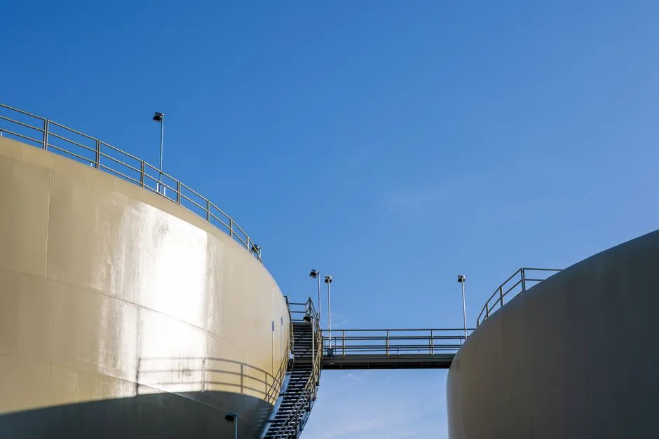
A hydrostatic level transmitter infers fill height from the head pressure of the liquid column (P = ρ·g·h) measured by a submerged pressure cell, while a laser level transmitter measures the distance from a top-mounted optics head to the surface via short-pulse time-of-flight on a narrow, near-infrared beam [S1][S4].
Both compete for the same physical variable (tank or silo level), but they solve it through opposite sensing geometries: one is contact-based and bottom-anchored, the other is non-contact and top-mounted, which drives every downstream decision on media, accuracy, and installation [S2][S6].
Operating Principles and Sensing Geometry
A hydrostatic level instrument is, mechanically, a pressure transmitter configured for level service: a flush or recessed diaphragm senses the head of the liquid column above it and outputs a level-proportional 4-20 mA or digital signal [S8]. The cell must be submerged, the process liquid density must be known, and the tank must be vented to atmosphere (or referenced against a separate leg) so that only hydrostatic head is read.
A laser level transmitter, by contrast, sits on top of the vessel or silo, fires a short light pulse downward, and times the return echo from the material surface, computing distance from the round-trip time and outputting the level as a continuous analog or digital value [S1][S3]. Because the beam is narrow and optical, the transmitter never touches the process, which is the dominant reason for choosing it in aggressive, hygienic, or solids applications.
Media Compatibility: Where Each Technology Wins
Hydrostatic transmitters are built for liquids and dense slurries, including water, wastewater, fuel oil, acids, and pulp stock, where the diaphragm is wetted by a known-density medium and the head pressure is a clean, linear function of depth [S2][S6]. They struggle in open-channel foam, in vessels where the liquid density varies with temperature or composition, and in any service where the diaphragm would foul or be chemically attacked.
Laser transmitters are designed for bulk solids (gravel, grain, plastic pellets, fly ash), slurries, and opaque liquids where a sight glass, ultrasonic, or radar reflection would be unreliable [S1][S4]. They are not suited to clear, low-reflectivity liquids, to foam surfaces, or to highly transparent media where the beam passes through the surface and returns from the tank bottom, since the device reads whatever surface returns the strongest echo [S3].
Accuracy, Range, and Beam Behavior
Hydrostatic accuracy is bounded by the pressure cell's reference accuracy (commonly 0.1%-0.2% of the calibrated span in industrial units) and by density uncertainty; a 1% density error translates roughly into a 1% level error across the full column [S8]. Practical measurement depth is set by the cell's range and the liquid head, typically up to a few tens of meters in a single leg.
Laser level accuracy is set by the time-of-flight resolution and the beam's footprint on the target: the narrower the beam, the smaller the surface feature it can resolve, and the less the reading is disturbed by silo walls, internal obstructions, or uneven fill [S1][S5]. Stand-off distance can extend to tens of meters for bulk-solid silos, with the optical head mounted well clear of dust, falling material, and high-temperature zones, and the beam can pass through protective windows or sight glasses without recalibration [S4].
Installation, Cabling, and Integration
A hydrostatic cell needs a process connection at or near the tank bottom, a stilling well or protective cage in turbulent services, and a vented or dual-leg pressure reference to cancel atmospheric effects; the cabling is standard 4-20 mA plus HART or a digital protocol carried on the same loop [S1][S2]. This makes it well matched to existing tank pads, sidewall nozzles, and differential-pressure wiring practices familiar to instrumentation crews.
A laser head needs a clear line of sight from the top of the vessel, a stable mounting flange or bracket aimed normal to the expected surface, and a window purge option in dirty service; it then drops into the same 4-20 mA / HART / Foundation Fieldbus / PROFIBUS PA ecosystem that a hydrostatic cell would, with no special wiring [S1][S4]. WirelessHART adapters are commonly used on both technologies for remote silos where running cable is uneconomic [S1].
Failure Modes and Plant Operating Limits
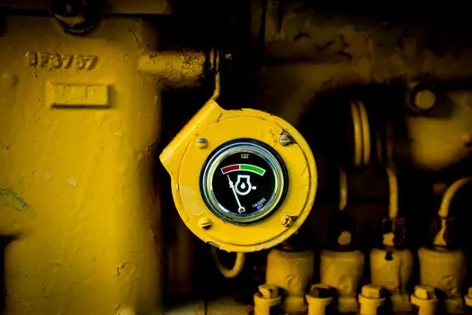
Hydrostatic failure modes are dominated by diaphragm fouling, coating, or chemical attack, by gas bubbles trapped at the cell face, and by density drift in multi-product or temperature-cycling service; each of these can shift the indicated level by the same percentage as the underlying disturbance [S2][S6]. Loss of the reference leg to atmosphere, or a plugged impulse line in legacy DP-style hydrostatic installations, shows up as a stuck or wildly drifting reading.
Laser failure modes are dominated by beam blockage: heavy dust, falling product bridging the optical path, condensation on the window, or a build-up on the sight glass can absorb or scatter the pulse and force the device into a hold-last or fault state [S3][S5]. The Class 1 / Class 2 laser safety classification also constrains mounting in occupied walkways, which can be a layout constraint in retrofit projects.
Decision Matrix: Hydrostatic vs Laser by Use Case
For clean liquids in vented, atmospheric tanks (water storage, diesel, mild chemicals), hydrostatic is the lower-risk pick: the cell is in its native service, accuracy is density-bounded, and installation reuses standard pressure-transmitter practices. For open vessels, sumps, and lift stations with a defined water column, a hydrostatic level transmitter with a submersible or screw-in body is the workhorse spec. [S1]
For bulk solids in silos, hoppers, chutes, and bunkers, laser is the workhorse spec: the beam reaches the surface from above, ignores the headspace dust cloud better than ultrasonic, and never contacts an abrasive, sticky, or hot product [S1][S4]. For aggressive chemicals, hygienic tanks, and any service where the wetted side must stay free of a sensor, a top-mounted laser also wins because the process interior is untouched [S5].
For slurries, thick stock, and pulp, hydrostatic and free-space radar are the more commonly cited reliable choices for plant mass balance, while laser is reserved for cases where the surface is opaque and the stand-off is short enough that beam divergence is acceptable [S6][S7]. In clear, low-reflectivity liquids, hydrostatic is usually the only correct answer, since a laser beam can penetrate the surface and return from the tank bottom.
Selection Criteria Recap

Match the technology to the medium first (liquid vs bulk solid vs slurry), then to the mounting geometry (submersion vs line-of-sight), then to the safety class (eye-safe laser classification, hazardous-area approval on the cell), and only then to the I/O layer. A wrong first cut on medium or geometry cannot be fixed by protocol choice: a laser mounted over a clear solvent, or a hydrostatic cell on a dry powder, will misread regardless of whether the loop is HART, Foundation Fieldbus, or wireless. [S5]
Track two signals over the next plant walk-through: how many top-mounted, line-of-sight positions on bulk-solid vessels are still served by older ultrasonic or cable-and-weight devices (candidates for a laser upgrade), and how many submerged hydrostatic cells on chemical tanks are overdue for diaphragm inspection or replacement (candidates for a like-for-like swap, not a technology change). The same I/O and DCS wiring makes either refresh a routine maintenance event rather than a capital project, which is usually the deciding economic factor.
The underlying component specifications are covered under capacitance level transmitter.
Background reading: Circular Saw TCO: Where the Real Money Goes Beyond Purchase Price.