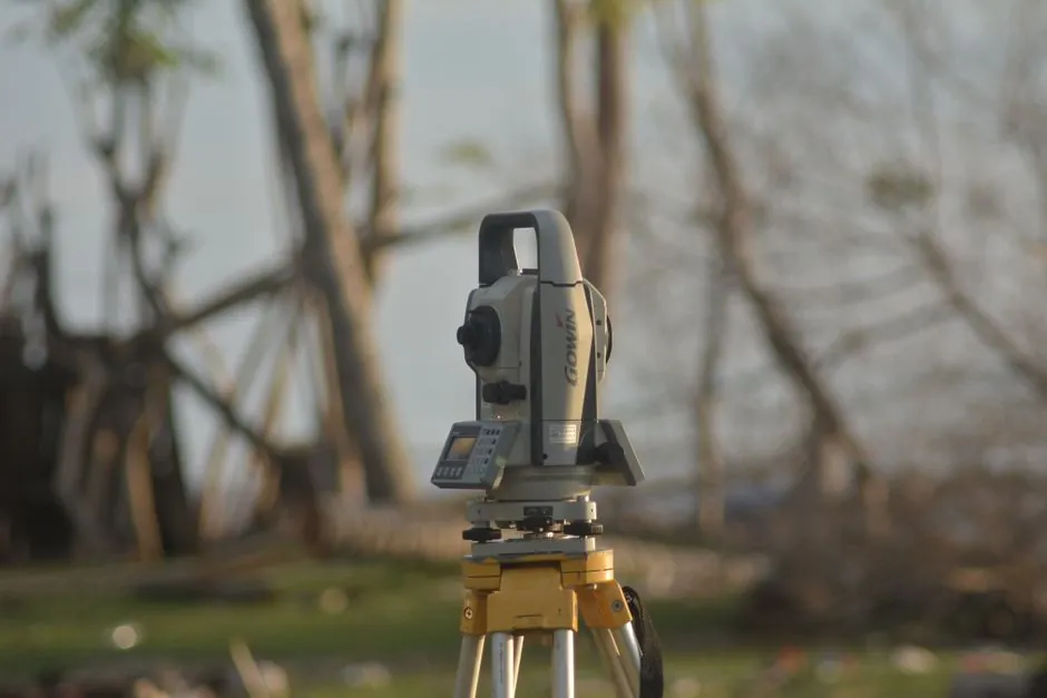
An automatic level is an optical leveling instrument that uses an internal pendulum compensator to keep the line of sight horizontal once the circular bubble is roughly centered, with field accuracy commonly rated at 1.5 mm to 3.0 mm per 30 m of double-run sighting depending on model class [S1].
Installation on a job site centers on four components: a circular bubble vial, a telescope with magnifier, a tripod with clamps, and a marked stadia rod, and a two-person crew is standard because one operator reads while the other holds the rod [S1].
Tripod Selection and Footing for Stable Readings
Tripod stability is the single largest contributor to repeatable automatic level accuracy on dirt, gravel, deck, or asphalt surfaces, because even a 1 degree tilt can push the internal compensator past its self-leveling range [S1]. Aluminum and wood tripods both appear in OEM kits, with extendable legs typically spanning 1.0 m to 1.7 m collapsed-to-extended, and the instrument head seated on a flat tripod plate via a 5/8-11 center thread common to most surveyors' automatic levels [S1]. Set the tripod with the head as close to level as the legs allow, press each foot firmly to displace loose material, and avoid placements where any leg crosses a recent trench or freshly placed formwork, since ground heave under load is a primary cause of mid-job drift [S1]. On RV hydraulic auto-level installations, the equivalent footing question is different: jacks must be mounted to the chassis frame near the front and rear axles with 7 to 8 in. of minimum ground clearance on the smallest SL-15 / SL-16 legs, scaling to 18 to 20 in. on 36 in. stroke AJ/AM/CT/SM units [S2].
Coarse Leveling with the Circular Bubble Vial
The circular bubble vial is the only manual leveling control a typical automatic level exposes, and the compensator handles the residual error, so operators center the bubble to within the vial's inner ring before the telescope is rotated to the backsight [S1]. On most automatic levels the vial sensitivity is 8 minutes to 10 minutes per 2 mm division, which corresponds to a residual tilt of roughly 0.15 to 0.20 degrees at the head; exceeding that pushes the compensator out of its capture range and the crosshair will appear to "wobble" or freeze off-target, a clear sign to re-center the bubble, not the instrument [S1]. Two installation tips follow directly from this: tighten all three foot screws evenly after coarse leveling, and avoid sitting or leaning on the tripod during readings, since the typical 1.5-3.0 mm per 30 m accuracy spec assumes a steady head, not a moving one [S1].
Two-Person Sighting Workflow: Backsight, Foresight, and Turning Point
Standard field practice calls for Person A to read the backsight on a stable point, pivot the telescope 180 degrees for the foresight, then continue in leapfrog fashion with turning points every 30-60 m to control cumulative error [S1]. The instrument's compensator typically self-corrects within roughly ±10 minutes of tilt, and a well-calibrated unit will hold 1.5 mm at 30 m under that envelope, but performance degrades sharply beyond ±15 minutes, which is why coarse bubble centering is non-negotiable before any rod is read [S1]. For RV auto-level systems the analog is a sequenced jack deployment: Power Gear owners report a three-stage automatic cycle that ends in a final "tweaking" phase, with the panel lights indicating current jack state, and Big Foot and Lippert systems use welded frame brackets plus a 4 AWG (or 2 AWG for runs over 12 ft) battery feed, matching the wire sizing rule of the Equalizer Systems installation manual [S2][S3]. For site-survey fundamentals and the related role of automatic leveling instruments in modern layout work, engineers should treat the bubble as a coarse gate and the compensator as a fine gate, with rod-reading protocol sitting on top of both.
Calibration, Test, and Acceptance Criteria
Acceptance of a freshly installed automatic level is verified with a two-peg test: set two stakes roughly 30 m to 40 m apart, take equal-distance backsight and foresight readings, then move the instrument to within 2-3 m of one stake and re-read; the resulting elevation difference between the two setups must agree within the published accuracy, typically 1.5 mm to 3.0 mm for a 30 m double-run, and any larger deviation indicates a collimation error, not a footing or bubble problem [S1]. When the test fails, do not adjust the compensator in the field unless the unit has a user-accessible calibration screw; send the instrument to a calibration lab or a manufacturer's authorized service center, since field disassembly of the compensator group commonly voids the warranty on mid-range optical levels [S1].
Comparison: Automatic Level vs Laser Level vs Manual Spirit Level
Choosing among the three common leveling technologies is a question of sight distance, crew size, and tolerance: an automatic optical level suits 30 m to 120 m two-person work at 1.5-3.0 mm precision per 30 m; a laser level covers single-operator layouts at 50 m to 300 m with roughly ±2 mm at 10 m typical accuracy on visible-beam self-leveling models; and a manual spirit level is the right tool only for short-range carpentry where the operator's eye can resolve a bubble under 5 m [S1]. For interior layout and finish work, the infrared level class offers a short-range indoor option, but it does not replace an automatic level for differential elevation work across a site. Cost and crew follow the same pattern: automatic optical levels typically require two people because a rod must be read, laser levels are single-operator, and manual spirit levels need one person plus direct line of sight to the workpiece [S1].
When NOT to Use an Automatic Level: Limits and Failure Modes
Automatic levels are not the right tool in three common field conditions: (1) sight distances beyond roughly 120 m where atmospheric shimmer and rod-reading parallax dominate the error budget, favoring a laser level or total station instead; (2) environments with sustained vibration, for example next to a pile driver or on a bridge deck under live traffic, where the compensator cannot settle inside its ±10 minute capture window; and (3) any layout where the tripod must be placed on recently placed concrete, frozen ground that is heaving with sun, or backfilled trenches that have not consolidated, since the published 1.5-3.0 mm per 30 m accuracy assumes a stable head [S1]. For RV platforms, similar "do not install" rules apply: hydraulic auto-level systems should not be fitted to a coach where the foot pad cannot be kept within the manufacturer's ground-clearance chart, where the +12 V cable run forces thinner than 4 AWG wire (use 2 AWG over 12 ft per the Equalizer Systems spec), or where the operator is unwilling to use jack stands whenever work is performed under or near the coach, as the OEM manual explicitly warns [S2].
Standards, Sourcing, and Warranty Boundaries
For surveying instrument work, factory calibration certificates and ISO 9001 quality system registration are the practical baseline a procurement team should request with any new automatic level, alongside a documented two-peg test result traceable to the unit's serial number. For hydraulic auto-level systems, the binding reference is the manufacturer's installation manual, with Equalizer Systems explicitly stating that "modification of any factory-supplied item may result in the denial of all warranty claims" and that Technical Support must be consulted before any deviation from the printed steps [S2]. Two-trackable signals for follow-up: monitor OEM release notes for revised ground-clearance charts on SL-series and AJ/AM/CT/SM-series legs, and watch for a Class C-specific auto-level installation guide from Lippert or Big Foot, which as of late 2025 was still a gap in publicly available documentation according to owner threads on Thor Forums [S3].
Background reading: Circular Saw TCO: Where the Real Money Goes Beyond Purchase Price.