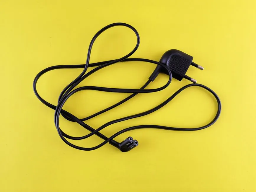
IEC 60228 fixes the maximum DC resistance of cable conductors at 20°C, governing every copper and aluminum cable sized under IEC 60287 and every voltage drop, current capacity, and short-circuit check that follows [S2]. The standard splits conductors into class 1 solid, class 2 stranded, class 5 flexible, and class 6 extra-flexible, with each class carrying its own ceiling at every nominal cross-section from 0.5 mm² up to 1200 mm² [S4].
For a 1.5 mm² plain copper conductor the limit is 12.1 Ω/km in classes 1 and 2, rising to 13.3 Ω/km in class 5 flexible and 13.7 Ω/km once the same conductor is tinned [S2]. A 120 mm² aluminum class 1 conductor is capped at 0.253 Ω/km, more than 1.6 times the 0.153 Ω/km figure for plain copper of the same cross-section and class [S4].
Plain copper class 1 and class 2: 0.5 to 1200 mm²
Class 1 solid and class 2 stranded plain copper share the same 20°C ceiling across the full IEC range: 36.0 Ω/km at 0.5 mm², 12.1 Ω/km at 1.5 mm², 4.61 Ω/km at 4 mm², 1.83 Ω/km at 10 mm², 0.727 Ω/km at 25 mm², 0.387 Ω/km at 50 mm², 0.193 Ω/km at 95 mm², and 0.0754 Ω/km at 240 mm² [S2][S4]. The table runs to 630 mm² plain copper at 0.0283 Ω/km, beyond which the standard stops publishing for copper because round compact conductors above 630 mm² are rarely used in fixed installation [S4].
Tinned copper in the same class adds roughly 1.7 to 2.0% to the resistance, lifting 10 mm² from 1.83 Ω/km plain to 1.84 Ω/km tinned and 1.5 mm² from 12.1 to 12.2 Ω/km [S4]. The differential grows at smaller cross-sections because the tin layer is a fixed process thickness, so its share of the cross-section is larger on a thin wire [S1].
Class 5 and class 6 flexible copper: the higher-resistance ladder
Class 5 and class 6 flexible copper conductors, used on leads, welding cable, and drag-chain wiring, run a notch above class 1 and class 2 because the finer strands raise the path length per unit mass [S2][S3]. At 1.0 mm² the ceiling is 19.5 Ω/km plain (40.1 Ω/km tinned at 0.5 mm²), 13.3 Ω/km at 1.5 mm², 7.98 Ω/km at 2.5 mm², 4.95 Ω/km at 4 mm², 1.91 Ω/km at 10 mm², 0.780 Ω/km at 25 mm², and 0.386 Ω/km at 50 mm² [S2][S4].
At the heavy end, class 5 plain copper lands at 0.0287 Ω/km for 630 mm², almost exactly 1.4% over the class 2 ceiling of 0.0283 Ω/km [S2][S4]. Designers should keep this in mind when the cable schedule lists "flexible" or "class 5" for fixed wiring; the change in resistance is small at large cross-sections but stretches the voltage-drop budget at 1.5 to 6 mm².
Aluminum conductors: where IEC 60228 actually caps them
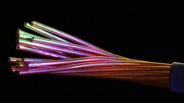
IEC 60228 only publishes aluminum limits from 10 mm² upward, because aluminum below that size is not standardised for fixed installation [S4]. Class 1 and class 2 aluminum values are 3.08 Ω/km at 10 mm², 1.20 Ω/km at 25 mm², 0.868 Ω/km at 35 mm², 0.443 Ω/km at 70 mm², 0.253 Ω/km at 120 mm², 0.125 Ω/km at 240 mm², and 0.0469 Ω/km at 630 mm², extending out to 1200 mm² at 0.0247 Ω/km [S2][S4].
Compared with plain copper at the same cross-section and class, aluminum runs 1.6 to 1.7 times higher, the ratio you would expect from the 1.724 / 2.826 × 10⁻⁸ Ω·m resistivities at 20°C [S2]. There is no class 5 or class 6 aluminum column in IEC 60228; if a flexible aluminum cable is offered, the table does not cover it and the manufacturer value should be used instead [S4].
Class 2 stranded detail: minimum wire count and tinned deltas
Class 2 stranded copper is not a single value; the standard pins a minimum number of wires at each cross-section, and the tinned column diverges further as size grows [S4]. At 0.5 mm² seven wires is the floor and the plain and tinned values are 36.0 and 36.7 Ω/km, a 1.9% spread. At 240 mm², 37 wires is the floor and the spread is 0.0754 Ω/km plain against 0.0762 Ω/km tinned, still about 1.0% [S4].
Class 2 stranded aluminum is also covered, with 6-wire minimums at 16 to 35 mm², climbing to 53 wires at 400 to 500 mm² and 91 wires at 800 to 1000 mm² [S4]. The 800 mm² class 2 aluminum limit is 0.0367 Ω/km and the 1000 mm² limit is 0.0291 Ω/km, identical to the class 1 figures at those sizes [S4].
Temperature correction: from 20°C to 70°C and 90°C
IEC 60228 is a 20°C specification, so the values above are not used directly in a voltage drop or current capacity calculation at the conductor's operating temperature [S5]. The same reference notes that copper at 70°C has 19.6% more resistance than at 20°C, and PVC and XLPE insulation ceilings of 70°C and 90°C are the two reference points most installation work uses [S5].
A 1.5 mm² plain copper class 1 conductor starts at 12.1 Ω/km at 20°C, becomes 14.47 Ω/km at 70°C, and 15.49 Ω/km at 90°C. The 240 mm² class 1 figure of 0.0754 Ω/km at 20°C scales to 0.0902 Ω/km at 70°C and 0.0966 Ω/km at 90°C, which matters when you are running a 63 A sub-main 80 m through a 400 V three-phase plant room [S5].
How these values are actually used
The 20°C IEC 60228 ceiling is the compliance benchmark for routine cable manufacture, the input to every voltage drop calculation that uses tabulated R rather than a manufacturer's number, and the basis for breaking-capacity checks in short-circuit studies, where Mitolo and others have shown that using 20°C nominal values and adjusting only for the short-circuit temperature bracket is the conservative, standardised path [S7][S8]. The same tables feed the power cable sizing workflow that runs from cable selection to protective device setting. Outside the tabulated range, the calculation falls back on the CENELEC CLC/TR 50480 form R = ρ₂₀ / S, with ρ at 1.724 × 10⁻⁸ Ω·m for annealed copper and 2.826 × 10⁻⁸ Ω·m for aluminum at 20°C [S1][S2].
For multi-core and triplex cables, IEC 60228 figures are used without correction; the lay-length factor only applies to AWG and kcmil conductors outside IEC 60228 scope, where IEC TR 62602 publishes the multipliers [S1]. When the manufacturer supplies an electrical resistance, that value already includes the lay correction and overrides the standard table for any cable outside the IEC 60228 tabulation [S1]. Cable design also depends on the DC supply feeding the run, and the related DC power supply load profile fixes the operating current that the 20°C ceiling has to be corrected against.
Trackable signals to watch next: a possible IEC 60228 edition 5 revision that would align 2500 kcmil values with the late-2024 aluminium 0.0119 Ω/km change already in edition 4 [S1], and any update to the IEC 60287 series on AC resistance that re-derives skin and proximity factors for the larger 800 to 1200 mm² aluminum range now being tabulated.
The underlying component specifications are covered under dc dc converter.
Background reading: Twin Hoists on a Single Girder: Specs, Sizing, and Long-Load Use.