The choice between an IEPE (voltage-mode) accelerometer and a charge-mode piezoelectric accelerometer is driven by temperature, cable length, and signal-conditioning architecture, not by which one is "newer" [S1][S2][S3].
Both designs use the same piezoelectric sensing element, but the IEPE variant places a tiny JFET (or hybrid) amplifier inside the sensor housing and converts the high-impedance charge into a low-impedance voltage right at the source, while the charge-mode design leaves that conversion to an external amplifier connected through a low-noise coaxial cable [S2][S4][S6].
How the two signal paths actually differ
IEPE stands for "Integrated Electronics Piezo-Electric" (the older trade name ICP refers to the same architecture from PCB Piezotronics); the integrating amplifier in an IEPE sensor is supplied through the same 2-wire twisted pair that carries the output, biased by a constant-current source that is typically regulated between 2 mA and 4 mA from an 18-30 VDC supply, with 20 mA used only on long-cable or high-drive variants [S3][S4][S8].
Charge-mode sensors output raw charge in picocoulombs (pC) with output impedance so high that the cable insulation, not the cable resistance, dominates low-frequency response; the cable must be a low-noise coaxial type and a separate in-line or rack-mount charge amplifier converts pC to a usable voltage [S1][S2][S6][S9].
Temperature ceiling: the single most decisive spec
Standard IEPE electronics stop working reliably around 248°F (120°C) because of the JFET/bipolar amplifier die inside, and even high-temperature IEPE designs (using special ASICs and high-temp bias resistors) only push the ceiling to about 329°F (165°C) [S3].
Charge-mode piezoelectric accelerometers have no active electronics at the sensing point, so the upper limit is set purely by the piezoelectric element, the housing, and the cable; with PZT or similar high-temperature crystals the operating envelope routinely extends to 500-700°F (260-371°C), and specialized charge-mode sensors (e.g., for gas-turbine health monitoring on the spool or for autoclave vibration) run to roughly 1200°F (650°C) [S3].
Conversely, at the low end, charge-mode sensors with low-temperature crystals can operate to about -320°F (-196°C), while IEPE units are usually clipped at the amplifier's own lower spec, commonly -65°F (-54°C) [S3].
Cable, noise, and low-frequency behaviour
IEPE systems tolerate long cables well because the in-head amplifier has already converted the high-impedance charge to a low-impedance voltage; the cable sees a voltage, so cable capacitance and triboelectric noise are largely irrelevant, and a 100 m run of ordinary twisted pair is routine [S2][S4][S8].
Charge-mode systems degrade rapidly with cable length: a charge-mode sensor specified at 1 pC/g can lose a large fraction of its sensitivity if driven through 30 m of standard coax, because cable capacitance and insulator leakage (especially at elevated temperature, where insulation resistance drops) form an unintended low-pass filter with the amplifier input; the cure is a low-noise cable (graphite-coated or hard-line dielectric), a length compensation step, or an in-line head amplifier that converts pC to voltage close to the source [S2][S6][S9].
Both designs are AC-coupled by nature, so neither can measure true DC; quasi-static (sub-Hz) measurements are possible but not reliable, and the engineer must budget the discharge time constant, which on an IEPE sensor is set by the bias network and on a charge-mode system by the amplifier input resistance in parallel with the source capacitance [S2][S4].
Cost, system complexity, and failure modes
IEPE sensors are more expensive per channel than the bare charge element (the integral JFET and bias network add BOM cost), but they save money on the system side: a single multi-channel DAQ with built-in 2-4 mA constant-current excitation per channel accepts IEPE directly, with no per-channel charge amp and no low-noise coaxial cabling [S3][S4].
Charge-mode setups are cheaper per accelerometer but need a discrete charge amplifier (one per channel) for laboratory-grade accuracy, and that amplifier has its own temperature and drift budget that is usually narrower than the sensor it is paired with, so the amplifier, not the sensor, often limits the measurement envelope [S1][S2][S6].
Common failure modes also differ: an IEPE sensor fails when the in-head amplifier dies (often signaled by the DAQ bias-voltage monitor going out of its 7-14 V "healthy" window, an open or short), while a charge-mode sensor can drift silently as cable insulation absorbs moisture; the cure is the bias monitor on the IEPE side and an insulation-resistance check on the charge-mode side [S4][S8].
Selection matrix: which to specify when
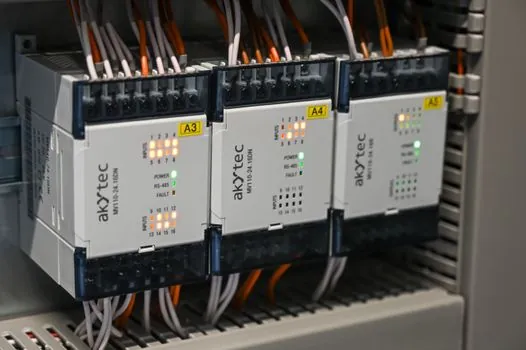
Pick IEPE (voltage-mode) for general-purpose rotating-machinery vibration (pumps, motors, fans, gearboxes), for any cabinet DAQ or PLC channel-count above a handful, for cable runs over about 10 m, and for any test bed where ambient stays under 120°C; the cost-per-channel is the lowest and the signal conditioning is built into the same 2-wire cable [S3][S4][S8].
Pick charge-mode when the measurement point is on a turbine casing, exhaust manifold, autoclave, forging die, or any location above 165°C, or when the application demands long-term stability under thermal cycling where semiconductor drift inside an IEPE would be unacceptable; budget a charge amplifier, a low-noise cable, and a length-compensation step on every channel [S1][S3][S6].
For a side-by-side decision view, a useful mental table is: (a) upper temperature, IEPE ~120-165°C vs charge-mode ~260-650°C+; (b) cable tolerance, IEPE tolerates 100 m+ of twisted pair vs charge-mode requires <10 m of low-noise coax unless an in-line head amp is used; (c) cost per channel, IEPE higher unit cost, lower system cost, vs charge-mode lower unit cost, higher system cost; (d) signal conditioning, IEPE uses a constant-current source (typically 2-4 mA from 18-30 V) and reads volts, vs charge-mode needs an external charge amp and reads pC. A signal conditioner page is the right cross-reference for the IEPE side, and an accelerometer overview covers the sensing-element side in more detail.
Standards, grounding, and data-acquisition integration
No single IEC or ISO standard fixes the IEPE constant-current value; the 2-20 mA / 18-30 V envelope is a de facto convention set by the major sensor vendors (PCB, Dytran, Kistler, Endevco, Brüel & Kjær) and supported by National Instruments' IEPE-capable DAQ modules (e.g., NI 9234) with built-in 2 mA excitation and AC or DC coupling options [S4][S6][S8].
Calibration of both families is anchored in ISO 16063-21 (primary calibration by laser interferometry) and ISO 16063-11 (secondary calibration by comparison), which define sensitivity in either pC/g (charge) or mV/g (IEPE) at a reference 159.2 Hz or 80 Hz, with phase tolerance typically +/-3% at the reference frequency; the same SI units and reference methods let the engineer mix IEPE and charge-mode channels on the same test stand without unit-conversion traps [S9].
For permanent machinery-protection installs, IEEE 344 / API 670-style vibration channels on utility or refining assets have historically used charge-mode sensors with seismic-grade charge amplifiers for the harshest cabinets, but the trend on new builds is IEPE into a SIL-rated signal conditioner, because the in-cabinet wiring simplifies and the bias-voltage health check maps directly to API 670 channel-OK logic; on a related decision axis, rotary vs linear encoder selection follows the same temperature-vs-system-cost trade-off, since both charge-mode and linear encoders move the front-end electronics off the moving part.
One watch-out worth flagging: in a high-voltage tester or large rotating-machine test cell, ground loops between the IEPE constant-current source and the data-acquisition ground can superimpose 50/60 Hz hum that swamps the accelerometer's own self-noise; the cure is to ground the IEPE cable shield at the sensor end only, and to use a DAQ channel with isolated constant-current excitation or an in-line IEPE isolation block [S2][S4].
Next signals worth tracking: vendor migration of high-temperature IEPE ASICs past the 165°C ceiling (if a credible part reaches 200°C+, the system-cost argument for charge-mode above the IEPE limit collapses), and any revision to the IEPE constant-current convention in the 2-4 mA range driven by 4-20 mA industrial-loop standards [S3][S8].