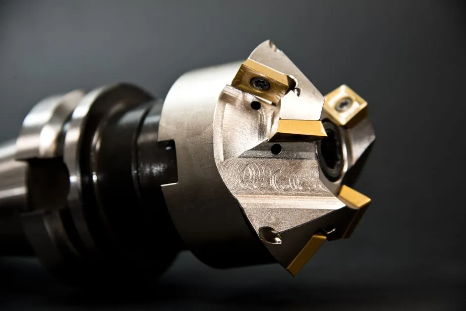
A linear encoder closes the position loop on the slide itself, so ballscrew lead error, coupling windup, and thermal expansion drop out of the accuracy budget; a rotary encoder closes the loop on the motor shaft, so every mechanical error between shaft and slide lands inside the position budget [S1][S5].
Selection is driven by four numbers: the axis's required positioning accuracy, the screw's lead error per foot, the controller's backlash-compensation quality, and the encoder's pulse count after quadrature (4x) multiplication. Rotary encoders up to about 5000 lines/rev are common in industry, yielding 20,000 counts/rev after 4x [S2]; linear scales commonly resolve 0.1 µm or better for the highest-precision axis work [S4].
Working principle and where each device physically sits
A rotary encoder is a code disc (optical) or magnetised ring (magnetic) read by a stationary sensor head; it attaches to the motor shaft or a gear/coupling downstream, and the controller counts pulses to infer shaft angle and, by gear ratio, slide position [S4][S7].
A linear encoder pairs a rigid scale (glass, steel tape, or magnetised strip) with a read head that rides along the axis; the head outputs incremental A/B pulses or absolute position codes, and resolution is set by the line pitch of the scale, typically 0.1 µm to a few µm for optical types [S4][S1]. Because the head is mechanically referenced to the slide, the reading is independent of screw lead, bearing stack compliance, and coupling torsional windup [S2].
Resolution, accuracy, and the quadrature math engineers misuse
Published PPR (pulses per revolution) on a rotary encoder is the line count before quadrature; the controller multiplies by 4, so a 5000-line/rev device delivers 20,000 counts/rev, not 5000 [S2]. On a 5 mm/rev leadscrew, 20,000 counts/rev resolves to 0.25 µm/count at the slide, which exceeds the practical accuracy of all but the best ground ballscrews.
On a linear scale the published specification is lines/mm (or µm pitch), and the same 4x rule applies; 0.1 µm resolution is achievable, but the datasheet distinction between resolution and accuracy matters: accuracy includes scale linearity, interpolation error, and thermal expansion of the scale itself, and is typically 2-5x worse than the raw resolution figure [S4].
Comparison: rotary (5000-line, 4x) vs linear (1 µm pitch) vs linear (0.1 µm pitch) on three decision criteria:
Cost per axis: rotary is lowest (compact, fits inside servo housing); linear at 1 µm pitch is mid-range; linear at 0.1 µm pitch is highest, especially in protected lengths above 1 m.
Slide-position accuracy: rotary is bounded by screw lead error plus backlash (typically a few µm to tens of µm for ground preloaded screws); linear at 1 µm is bounded by scale accuracy (a few µm over the travel); linear at 0.1 µm is bounded by scale accuracy plus interpolation error (sub-µm on short axes).
Failure-mode risk: rotary fails safe (lost pulses are usually detectable, no false absolute position); linear is exposed to contamination on the scale and read-head crash damage, and an absolute linear scale also requires battery-backed or multi-turn encoding for power-loss recovery [S1][S4].
When the screw itself is the limit, not the encoder
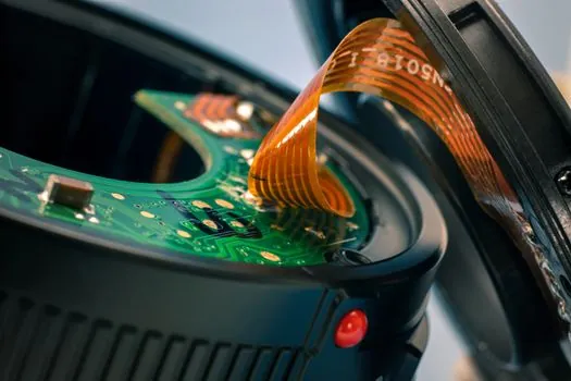
If the machine uses a precision-ground, preloaded ballscrew rated at 0.0005 in/ft lead error (about 12 µm over 1 m of travel), a high-count rotary encoder is sufficient: the screw's repeatable error is the dominant term, and a linear scale will measure that error faithfully but cannot correct it [S2].
Conversely, on a standard rolled ballscrew (typical lead error 0.003-0.005 in/ft, or 75-125 µm/m) the screw error dominates the system by an order of magnitude over a 0.1 µm linear scale's own accuracy, so adding a linear scale gives meaningful real-axis improvement; adding only a higher-resolution rotary encoder does not [S2][S5].
Application fit: rotary, linear, or both
Rotary encoders are the right pick for motor commutation, speed control on conveyors, robot joint angle, and any axis where the controlled variable is shaft angle, not slide position; they are also the practical choice on existing machines where pulling a linear scale along the axis is mechanically invasive [S1][S4].
Linear encoders are specified on precision grinding machines, high-end machining centres, semiconductor lithography stages, and CMMs, where the goal is to measure the slide, not infer it; for straight-line axes demanding the highest speed at sub-µm accuracy, a linear encoder is the optimal choice [S4].
Dual-feedback arrangements (rotary on the motor for commutation and velocity loop, linear on the slide for the position loop) appear on premium gantry machining centres and large roll-to-roll web handlers, where the cost of two encoders per axis is justified by the elimination of mechanical error sources from the position loop [S2][S6]. The same dual-loop logic shows up in linear actuator sizing, where the actuator's own position sensor pairs with an external scale on high-stakes axes.
Output signals, protocols, and integration gotchas
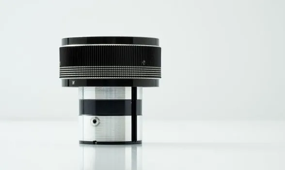
Incremental outputs are TTL/HTL square waves (A/B plus index Z) for both encoder families, and Sine/cosine 1 Vpp analogue outputs are common on higher-resolution devices for finer interpolation in the drive [S1][S4].
Absolute outputs include SSI, BiSS-C, EnDat, and Hiperface DSL; these matter for safety-rated axes and for machines where re-homing after a power interruption is unacceptable, such as articulated robots and press-feed lines [S1].
Backlash compensation in the controller is mandatory when the loop is closed on a rotary encoder with any gear, coupling, or leadscrew in the drive train; even with a linear encoder on the slide, backlash compensation is still required for most leadscrew-driven axes because the slide can rock against preloaded nut clearance under reversal [S2].
Environmental limits and where each technology fails
Optical encoders (both rotary disc and linear glass scale) deliver the highest resolution and are immune to external EMI, but the read head and scale are vulnerable to dust, oil mist, and coolant, and the glass scale can shatter on impact [S1][S4].
Magnetic encoders tolerate contamination and shock far better, but their pole-pair spacing caps the maximum counts/mm; they are the standard for outdoor and heavy-industry applications where optical glass would fail [S4]. For machines that also carry heavy rotary hammer tooling, shock loading on the scale head is a routine failure mode, so magnetic scales or recessed protected scales are specified.
Capacitive linear encoders occupy a niche for specific non-metallic or non-magnetic scale materials; resolution is generally below optical glass but above low-end magnetic [S1].
Decision checklist for the next retrofit or new build
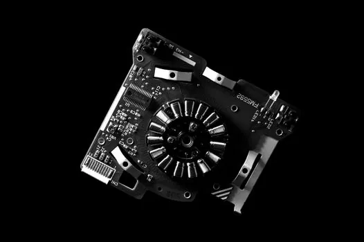
Use a rotary encoder when the controlled variable is shaft angle, the screw is precision ground and preloaded, the axis is in a contaminated environment, and cost per axis must stay low. Use a linear encoder when slide-position accuracy below 5 µm is the spec, the screw is rolled or shows measurable thermal growth, or the machine must hold tolerance over long travels (1 m and above). Use both when the axis is large, the screw error is significant, and the position loop must close on the slide while the velocity loop closes on the motor [S2][S4][S5].
Trackable signals for spec refresh: ballscrew lead-error class (ground vs rolled, with published µm/m figure), required axis accuracy and repeatability in µm, controller backlash-compensation resolution in counts, and whether the machine carries out re-homing on power-up or demands absolute feedback [S2][S4]. For a related comparison on the mechanical side of motion control, see the rotary drilling rig and linear bearing reference pages when sizing the bearing stack that the encoder will be measuring against.
See also our earlier report, Rewind vs Replace: Choosing When a Failed Power Transformer Is Worth Saving.