
Field data on rotary hammer and impact drill bit failures clusters into three dominant modes: tip chipping, hole drift, and bit jamming, each with distinct root causes tied to material grade, operator technique, and thermal load [S1]. A separate body of evidence from down-the-hole (DTH) drilling confirms the same physics on a larger scale, where impact end-face fatigue, gauge-button wear, and spline failure drive bit retirement [S2].
On masonry and reinforced concrete, an impact drill converts rotary motion into percussive blows at typical frequencies in the low kilohertz range, and it is the percussive interface, not the rotation, that destroys most bits prematurely. Understanding the failure mode is the first step in writing a spec that survives a real jobsite.
Tip Chipping: The Most Common Field Failure
Impact overload from forcing a bit through rebar or dense aggregate is the leading cause of tip chipping, with instantaneous impact energy exceeding the carbide's fracture limit [S1]. On C50 concrete, a standard YG8C tungsten carbide tip chipped within 5 minutes of continuous drilling in field trials, while a YG11C upgrade completed the same hole pattern without fracture [S1].
Thermal stress is the second major contributor: continuous operation heats the tip, thermal cycling generates micro-cracks, and a 2-hour uninterrupted run reliably produced thermal chipping in documented cases [S1]. The fix is mechanical discipline: 30-second cooling breaks every 10 to 15 holes, plus a start RPM held in the 300 to 500 RPM range to keep initial impact energy below the chipping threshold [S1]. Material matching matters as much as technique, since C40+ concrete requires YG11C or higher hardness grades to avoid the brittle-fracture cascade also seen in DTH button carbides [S1][S2].
Hole Drift: Precision Control Standards
Hole drift on impact-drilled installations arises from four mechanisms: start deflection on uneven surfaces, rebar deflection toward the path of least resistance, density variations in aggregate, and tool weight imbalance from operator fatigue [S1]. Precision control is graded by application: general construction tolerates deviation up to 5 mm per 100 mm of depth, precision installation requires 2 mm per 100 mm, and chemical-anchor bores are held to 1 mm per 100 mm [S1].
The pilot-hole method, a 3 to 5 mm pilot followed by progressive diameter increase, is the most reliable correction, while cross-head bit geometry resists skating on startup [S1]. Staged drilling with alignment checks every 50 mm of advance prevents the cumulative drift that triggers rebar strikes in deeper holes. For applications where structural safety depends on anchor position, support stands or guidance fixtures are the only way to hold the precision-installation tolerance under continuous hammer impact.
Bit Jamming: Evacuation and Safe Release
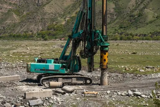
Bit jams in impact drilling come from four primary causes: dust accumulation in deep holes where chip clearing is inadequate, rebar entrapment where the bit wedges in rebar gaps, hole collapse around loose concrete or voids, and thermal expansion that binds the bit against the hole wall [S1]. In DTH service the same problem appears as gauge-button wear and body shrinkage, where the bit's outer diameter decreases until the end face contacts the rock directly [S2].
The safe-release procedure is fixed: cut power immediately, attempt reverse only if the tool supports it, and never apply leverage to the chuck or gearbox housing [S1]. A 30-second rest between holes doubles as a thermal management step and a jam-prevention step, since the bit contracts before the next engagement. For deep-hole work, the rule of thumb is to withdraw and clear dust every 10 to 15 holes, which matches the cooling cadence and keeps the evacuation channel open.
Carbide and Body Wear in Percussive Service
In DTH bits the carbides fail by three documented modes: abrasion from rock particles scraping the gauge button, broken buttons from stress concentration in hard strata, and button loss when the surrounding body wears [S2]. The same physics applies to smaller SDS-Plus and SDS-Max impact drill bits, where the carbide insert is the rock-breaking component and the steel body is the structural carrier.
Body failure in DTH service follows a predictable sequence: impact end-face damage forms a crater under repeated piston blows, fine cracks initiate at stress concentration points, and plastic deformation spreads until the face spalls [S2]. Spline failure is a separate body mode, where reverse torque and impact vibration create stress concentration at the drive interface, one tooth yields, and the remaining splines overload in cascade [S2]. For an impact driver or impact drill, the analogous component is the chuck and bit shank, where worn splines manifest as slipping under load and are the precursor to shank fracture.
Comparison: Failure Modes, Causes, and Prevention Levers
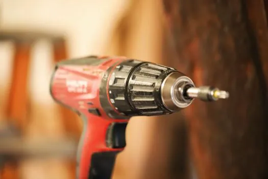
Across the three dominant failure modes, prevention maps to specific operator and specification actions. Chipping is controlled by carbide grade selection (YG11C for C40+ concrete), start RPM (300 to 500), and a 30-second cooling break every 10 to 15 holes [S1]. Drift is controlled by pilot-hole sequencing, cross-head geometry, and a guidance fixture for precision work, with the 1 mm/100 mm chemical-anchor tolerance as the strictest benchmark [S1].
Jamming is controlled by dust evacuation cadence and immediate power cutoff on binding, with thermal expansion as the hidden multiplier that ties all three modes together [S1]. On larger rotary hammer and DTH rigs, the same comparison extends to body fatigue: impact end-face life is set by piston frequency and rock hardness, while spline life is set by torque reversals and vibration amplitude [S2]. Buyers who spec a tool should request the manufacturer's chipping, drift, and jam-failure data per substrate, since the same tool can deliver a 5-minute or a 5-hour service life depending on the matched bit grade and the operator's adherence to the 30-second cooling interval [S1].
Standards, Sourcing, and Equipment Selection
Concrete-grade and rebar-detection references are the practical standards for impact drill bit selection, while structural-anchor installation tolerances come from the chemical-anchor manufacturer's published hole-position limits, typically 1 to 2 mm per 100 mm depth for post-installed rebar applications [S1]. For construction machinery and equipment fleets, the equivalent reference is the OEM's impact-energy and blows-per-minute rating, which sets the upper bound on the bit grade the tool can drive without chipping.
Trackable signals for the next planning cycle: the shift from YG8C to YG11C carbide grades on C40+ concrete sites, where the upgrade eliminates the 5-minute chipping failure mode documented in field cases [S1]; wider adoption of pilot-hole protocols on chemical-anchor bores to hold the 1 mm/100 mm tolerance; and routine replacement of impact-driver chucks at the first sign of spline wear, since the cascade-failure pattern in DTH service applies directly to smaller percussive tools [S1][S2]. For sites where bit consumption has been a line-item complaint, industrial fastener buyers and concrete-tooling buyers share a common lever: matched-grade consumables and documented cooling intervals cut per-cycle cost more reliably than chasing a cheaper bit price.