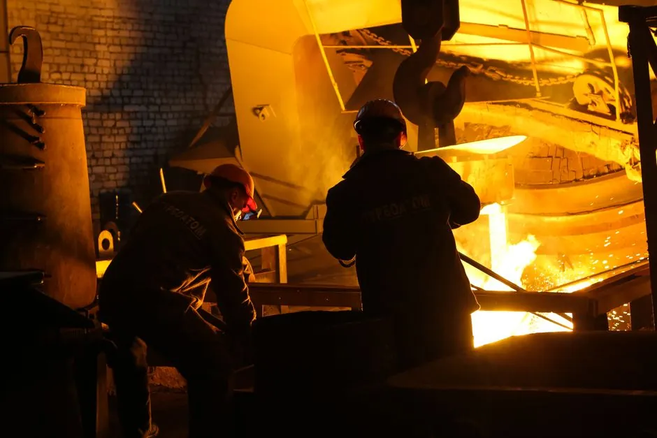
An induction furnace is the primary melter in most pump and valve casting lines, and its downtime is bound to the plant's pouring schedule, not to the furnace itself; a single burned coil can halt a shift of valve body pours and stall a pump housing run mid-batch [S1].
Pump and valve production stresses induction equipment in three specific ways: long holding cycles for ductile iron and stainless valve bodies, frequent alloy swaps between carbon, stainless, and bronze grades, and tight metallurgical windows for pressure-containing castings. A preventive program built around the cooling circuit, the vacuum system (where used for stainless or high-nickel alloys), and the refractory lining maps directly to those stresses [S1][S4][S5].
Cooling Circuit: The Single Most Common Failure Path
Cooling water is the failure mode that destroys induction furnaces fastest, because coil and power supply heat loads must be removed continuously or the copper coil anneals and shorts within minutes [S1][S4]. A 12.5 t/h medium-frequency coreless installation at a ductile iron foundry documented multiple coil burnouts when cooling capacity fell behind installed furnace load, with the plant losing entire coils and tripping out on over-temperature during peak shift demand [S4].
Daily checks that prevent the same failure on a pump/valve line: confirm flow rate and return temperature on every coil and power supply against a written baseline, log deviations, and replace any filter showing a pressure drop above the OEM threshold. Cooling water quality matters as much as flow: hardness, suspended solids, and biological growth foul tubes and scale the hot face of the coil, so conductivity and pH should be trended weekly and the side-stream filter cleaned on a fixed interval rather than on failure [S1][S4]. A maintenance-grade induction furnace program treats the cooling loop as a subsystem with its own PM schedule, not as part of the furnace.
Vacuum Integrity for Stainless and High-Nickel Valve Alloys
Pump and valve shops melting stainless, duplex, or nickel-based alloys typically use induction-heated vacuum furnaces, and leak rate is the variable that determines whether carbon and nitrogen pickup stay inside spec for pressure-containing service [S2][S3][S5]. The door O-ring is the most frequent leak path and is recommended for quarterly replacement as a baseline, with monthly inspection for cracks, gouge marks, and loss of elasticity, plus a thin film of vacuum grease that produces a visible sheen without excess [S3].
Helium leak detection is the standard for finding small leaks that pressure-decay tests miss, and the chamber must be leak-checked after any flange break, feedthrough service, or hot-zone rework [S2][S5]. O-ring materials for typical vacuum service in this class of furnace include Buna-N, silicone, and Viton, with common squish rates of 20-50% for reusable static seals; the material choice should follow the OEM manual and the highest process temperature seen at that joint [S2]. Pipe thread fittings in vacuum or gas service must be sealed with a PTFE-based pipe dope such as Swak rather than PTFE tape, because tape shreds and migrates into the chamber over time [S3]. For work on oil diffusion pumps, the pump must cool to ambient before service, since the oil reaches 240 deg C (464 deg F) and reacts explosively with air if the fill port is opened hot; silicone-based diffusion pump fluids eliminate that specific hazard [S2].
Refractory and Crucible: The Lining Decides Melt Quality
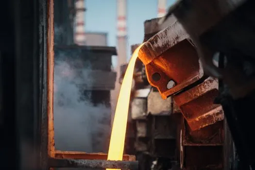
For coreless furnaces in pump/valve work, the refractory lining is the consumable that most directly governs melt cleanliness and operator safety, because a steel or iron breakthrough into the coil is both a fatal-coil event and a lost melt [S1][S5]. Inspect the lining before every campaign, looking for cracks, glaze, and erosion bands at the slag line; document thickness with a depth gauge at marked locations and trend the readings so erosion rate is visible, not anecdotal.
Channel furnaces used for holding and pouring pump and valve castings carry a different risk profile: the inductor channel and the connecting loop are the wear points, and metal circulation, not coil temperature, is usually the first symptom of a refractory problem [S1]. When lining wear approaches the OEM minimum thickness, schedule a re-line during planned downtime rather than running to failure, because an unplanned breakthrough during a pour cycle typically costs more in lost melt, damaged coil, and cleanup than a planned re-line [S1]. Crucible and lining material must match the alloy being melted; mixing grades shortens lining life and is a documented contributor to premature failure [S5].
Power Supply, Coil, and Electrical Connections
The induction coil, water-cooled leads, and the power supply are the third maintenance cluster, and the failure signature is arcing, not gradual drift, so connection torque and lead routing deserve the same attention as the coil itself [S1][S5][S6]. Water-cooled leads must be cross-polarized on a four-lead arrangement, and they must be kept clear of any conductive or metallic hardware that could create a stray current path; both rules are stated explicitly in published safe-maintenance guidance and are easy to violate during a coil change [S6].
Acceptance criteria after any coil or lead service: insulation resistance to ground should be greater than 10 megohm on a healthy hot zone, with any reading below 2 megohm treated as a stop-work condition requiring further investigation before the next heat [S3]. Thermocouples in induction-heated vacuum furnaces are consumables, not instrument-grade sensors, and should be calibrated on a fixed interval and replaced proactively rather than after a drift is suspected, because vapor pressure from reactive metals accelerates degradation [S5]. Daily logging of forward power, reflected power, frequency, and DC bus voltage gives the maintenance team a trendable baseline, and a sudden jump in reflected power is the earliest indicator of a coil or lead problem [S1][S5].
Comparison: Where Each Maintenance Lever Earns Its Budget
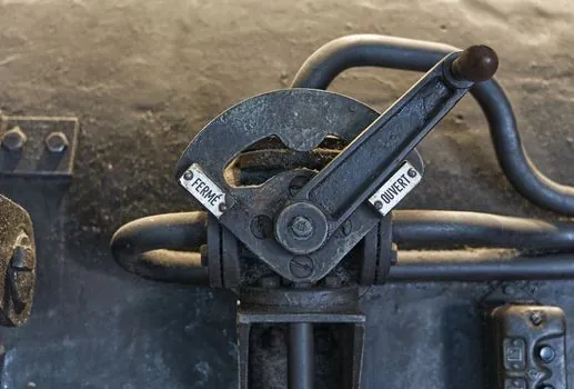
Four maintenance levers can be ranked against three criteria that matter to a pump/valice foundry: cost of the failure it prevents, frequency of intervention required, and skill level of the technician who can do the work [S1][S3][S4][S5]. Cooling-circuit care ranks highest: it prevents the most expensive failure (coil burnout), runs on daily rounds by trained operators, and uses standard water-treatment skills already present in most plants. Vacuum integrity is second: leak checks and O-ring service are quarterly to monthly, require a technician familiar with leak detectors, and prevent metallurgical rejects that are hard to trace after the fact. Refractory inspection is third: it prevents the most dangerous failure (melt breakthrough) but is inspection-driven and depends on the operator's discipline more than on tooling. Electrical and coil checks are fourth on cost-prevented but first on safety criticality, so they belong in the same lockout-tagout block as any chamber entry [S1][S3][S5].
Documentation, Spare Parts, and Operator Skill
Maintenance records are the lowest-cost, highest-return piece of an induction furnace program, because trend data on coil water temperature delta, reflected power, and lining thickness is what turns a surprise into a planned shutdown [S3][S4]. Spare parts should be staged against the plant's mean time to repair on the items that stop production: at minimum one set of O-rings for every flange on the furnace, one thermocouple of each type in use, a spare filter set for the cooling loop, and the OEM-specified refractory material in the quantity required for one full re-line [S1][S3][S5]. Operator training is the multiplier: documented pre-shift checks written in the plant's working language and reviewed during the shift handover catch most of the issues that become incidents on the next shift, and a 10-minute daily walk-around is consistently credited in published guidance with preventing the majority of unplanned shutdowns [S1][S4]. A casting mold spec program that feeds back melt and pouring data into furnace PM intervals will tighten the loop between casting defects and furnace condition, which is the kind of cross-discipline data pump and valve QA teams can act on.
Trackable signals for the next review cycle: cooling loop conductivity trend against the OEM limit, door O-ring replacement date versus the quarterly target, lining thickness delta from the last campaign, and reflected power deviation from the established baseline. Each of these is a number, not an opinion, and each maps to a specific induction furnace component that the maintenance planner can act on. Foundries that publish these four numbers on a weekly dashboard typically see unplanned downtime fall into a single-shift-per-quarter band rather than the multi-shift-per-month pattern of unmonitored plants [S1][S4].
For component-level specifications, see construction machinery and equipment, and lamps and light fittings.