The dominant failure mode on a newly commissioned industrial gear unit is not the gear steel — it is the installation sequence. Bearings fail from misalignment, contacts spall from incorrect backlash, and seals leak because the housing was never squared to the driven shaft [S3][S4][S5].
A reliable install compresses into five pre-rotation gates: PPE and work-area clearance, mounting arrangement (straddle vs overhung), soft-foot and shim correction, laser or dial-indicator alignment to 0.05–0.10 mm, and lubricant grade matched to ambient [S2][S3][S5]. A six-step pre-energisation checklist from an industrial-gearbox OEM lists five inputs that must be confirmed before coupling: gearbox type, frame size, cantilever and side-load rating, oil type, and input power/speed [S2].
PPE, Lifting, and Work-Area Preparation
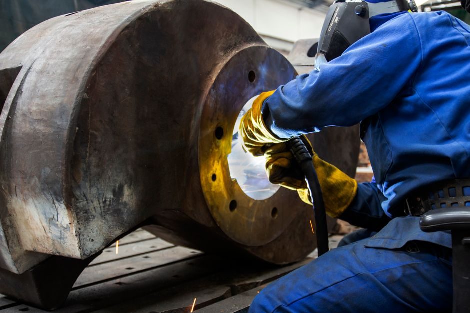
Industrial gear units routinely ship in the 50–2 000 kg range, and the first injury exposure is lifting, not rotation. Specified PPE for any gearbox handling is safety gloves, helmet, eye protection, and steel-toed boots; loose clothing and jewellery are removed before sling work [S3].
Workspace preparation is a measurable gate: clear a radius of at least 1 m around the install footprint, eliminate trip hazards from chain falls and air hoses, and verify illumination above 300 lux at the coupling face so dial-indicator readings are not misread. The lift itself should use a sling rated at 1.25× the gearbox mass and a spreader bar on units over 100 kg to prevent housing distortion that would warp the bearing bores [S3]. Skipping the spreader bar on a 500 kg helical unit is a known cause of post-install bearing brinelling, even when the shaft alignment is correct.
Mounting Arrangement: Straddle vs Overhung
Straddle mounting — two bearings on each side of the gear or pinion — is the default for industrial and heavily loaded applications because it constrains both ends of the shaft against deflection and axial migration. When gearbox geometry or shaft length forces a compromise, the element carrying the higher radial load gets the straddle mount, and the lighter-loaded member is overhung on a single bearing [S5].
Where the gear is free to drift axially on its bearing inner-race clearance (shaft end play), the gear must be located in its normal running position before the contact pattern is checked; otherwise the pattern you read is not the pattern the gear will run with. This single rule is the most common source of "the pattern looked right on the bench but is off-centre once loaded" complaints in field service reports [S4][S5]. For a deeper taxonomy of which gear style suits which duty, the industrial gear type spec map lays the parallel-shaft, helical-bevel, and planetary options against load and speed.
Shaft Alignment: Soft Foot, Shim Stack, and Indicator Targets

Soft foot — a housing distortion that lifts one foot off the baseplate when the bolts are torqued — must be eliminated before any alignment is recorded. Correction is a shim stack under the offending foot, with the stack kept to four shims or fewer to avoid stacking tolerance creep; anything above 0.05 mm of indicator movement under bolt torque means re-shim, not re-align [S5].
For coupled gear-motor sets, the acceptance window is 0.05 mm offset and 0.05 mm/m angular on a flexible coupling, and 0.03 mm on a rigid coupling. Laser alignment systems reach this in two iterations; dial-indicator work usually takes three to four. Coupling manufacturer data sheets always override general guidance — a 0.10 mm spec on a particular gear-type coupling is a contractual limit, not a suggestion [S3][S5].
Where the gearbox drives a chain or belt, the additional gates are cantilever load and side-load. SDT's pre-install intake form explicitly asks for cantilever and side-load figures alongside size and oil type, because over-running those numbers on the first 30 minutes of rotation is the fastest path to premature bearing failure [S2].
Contact Pattern and Backlash Verification
Contact pattern (the load-bearing mark left by marking compound on the tooth flank) tells you whether centre distance, parallelism, and tooth lead are correct. The check is performed with the gear in its normal running axial position, the housing torqued, and a light load applied to take up the slack side of the mesh [S4].
Backlash — the circumferential clearance between non-driving flanks of mating teeth — is the second half of the same gate. Industrial helical and parallel-shaft gears typically run 0.04–0.10 mm of backlash per module, with the exact value called out on the gear drawing; worm pairs run higher, and planetary stages are set by the carrier, not the ring gear [S4][S5]. Both figures are stamped on the OEM data sheet — if the drawing and the unit disagree, the drawing wins and the unit is re-shimmed. Shortcuts on the compound application (too much, too thick) produce a false pattern that hides the real error; the standard practice is a thin, even coat applied with a brush across the full face width [S4].
Lubrication, Oil Type, and Pre-Run Checks
Oil type is the single most-mis-answered field on a gearbox commissioning sheet. The correct viscosity grade is set by ambient temperature, gear type, and input speed — for example, ISO VG 220 mineral oil is the common industrial default at 0–40 °C ambient for helical-bevel units, while worm gears usually need ISO VG 460 with EP additives to handle the sliding contact [S2][S5].
Pre-rotation checks run in this order: (1) oil level at standstill on the correct dipstick or sight glass, with the unit level; (2) breather installed and clear; (3) guards in place; (4) rotation by hand for at least two full input revolutions to confirm no binding; (5) 30-minute no-load run with temperature and vibration logged at 5-minute intervals. Bearing housing temperature stabilising below 90 °C on mineral oil and vibration below 4.5 mm/s RMS (ISO 10816-3 Class 1 on a small unit) are the standard "ready for load" gates [S5].
The full gearbox OEM pre-install intake — gearbox type, size, cantilever load, side load, oil type, and input power — is also the basis for the supplier shortlist; a vendor that cannot answer those five items on the first call is not ready to quote.
Final trackable signal: record baseline vibration spectrum and bearing temperature at the 30-minute no-load mark, store it with the unit serial number, and trend it against the 500-hour, 2 000-hour, and 4 000-hour checks. A 3 dB rise in 1× shaft frequency or a 5 °C drift on a stable housing within the first 1 000 hours is the earliest actionable flag — fix alignment and foot flatness before changing the oil grade. For more on selecting the right gear reducer style against load and duty, the worm-gear reducer spec boundaries piece covers the materials, ratios, and thermal limits of the worm family. A side-by-side treatment of industrial gear units in the encyclopedia rounds out the spec vocabulary used in this install sequence.
Spec-level background on the components involved: linear guide, and crossed roller guide.