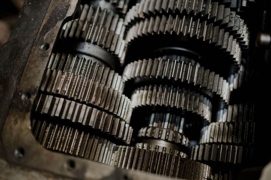
A complete industrial gearbox is not just its gears: it is a forged or cast housing, heat-treated shafts, ground or hobbed teeth, matched rolling-element bearings, and a sealed lubrication system, all assembled to a target AGMA quality grade and validated on a loaded test stand. Manufacturing yield, lead time, and total cost of ownership are decided in the first three stages — material selection, blank forming, and rough machining — not in the gear cutting cell that marketing usually photographs [S4][S5].
Planetary, helical-bevel, worm, and parallel-shaft units share roughly the same process flow; they differ in which workholding and cutting strategies are used inside each stage and in the AGMA/DIN class they must hit. Sourcing decisions should be driven by the application band: AGMA 8–9 (DIN 8–9) covers general industrial gearboxes, while AGMA 12–13 (DIN 4–5) is the band for automotive transmissions and aircraft engines [S5].
Stage 1 — Forging, Casting, or Powder-Metal Blank Forming
Cast iron, cast steel, forged steel (typically AISI 4140 / 42CrMo4), and ductile iron are the four blank families a process engineer chooses between for a gearbox housing or gear blank, with material selection governed by AGMA guidelines on tensile strength, endurance, and ease of machining [S3]. Casting — green-sand, shell, or V-process line routes — is the default for large gears over 6–10 ft (≈1.8–3.0 m) in diameter, where forging presses become uneconomical, while forging is preferred for high-stress pinions and helical gears that see cyclic tooth-bending loads [S3][S4].
For powder-metallurgy gears, the constraint is part size: PM blanks are economical for small module gears below roughly 100 mm pitch diameter, but cannot match the impact toughness of wrought steel above that envelope. Material choice is also a function of subsequent machining — bronze and brass gears machine easily but cap out at lower contact stress; case-hardening steels such as 16MnCr5 and 20MnCr5 require carburising capacity in the heat-treatment shop, which a buyer must verify before placing a forged-pinion order [S3].
Stage 2 — Rough Machining of Housings, Shafts and Gear Blanks
Rough machining removes 60–80 % of the stock left after forging or casting and establishes the datum faces that every downstream operation depends on: bearing seats, pilot bores (later verified with an industrial borescope), bolt-pattern faces, and gear-blank OD/ID concentricity. On a helical-bevel or planetary housing, boring the carrier and main bearing pockets to within 0.02–0.05 mm is the tolerance that decides whether the assembled unit holds its rated AGMA class or slips a grade [S4].
CNC turning and 5-axis milling dominate this stage; carbide inserts running at 150–250 m/min cutting speed on mild steel housings are typical. Skiving and turn-broaching have replaced some shaping operations for internal gears and splines because they cut cycle time roughly in half on modules above 2.0. The economic trade-off is fixture cost: skiving needs a precision pre-machined bore, so the cost win only appears at medium-to-high lot sizes [S4].
Stage 3 — Gear Cutting: Hobbing, Shaping, Skiving, and Broaching
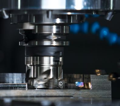
Hobbing is the highest-volume process for external spur and helical gears up to about module 6–8; gear shaping is used for internal gears, large modules, and clustered-shaft gear clusters that a hob cannot reach; skiving covers hardened external gears in the AGMA 8–10 band where finish hobbing is no longer possible; and broaching makes high-precision internal splines and blind keyways in a single pass [S3][S4]. For the soft-finish pass before heat treatment, hobs run at 80–120 m/min with depth-of-cut strategies that hold pitch error below 8–12 µm on a module 4 gear, which corresponds to roughly AGMA 9 [S5].
The clutch-gear profile work documented for high-productivity cells shows that profile-shaping and hobbing can be sequenced so that roughing, semi-finishing, and finishing happen in a single setup, cutting floor-to-floor time by 30–40 % versus three-machine flow on lot sizes above 200 pieces [S1]. The trade-off is machine rigidity: a 5-axis turn-mill cell with hobbing spindle delivers the productivity but locks the process to a single platform, which becomes a risk if that OEM exits the market.
Stage 4 — Heat Treatment: Carburising, Quenching, and Tempering
For case-hardened gearing, carburising at 880–930 °C followed by oil or polymer quench and a 160–200 °C temper drives the surface hardness to 58–62 HRC with a case depth of 0.8–1.5 × module for industrial gearboxes, and 1.5–2.0 × module for heavy industrial and wind gearboxes [S4]. Through-hardened pinions (4140, 4340) run 28–34 HRC after quench-and-temper and are used where impact loading dominates over surface contact stress.
Distortion control is the real engineering problem in this stage: a carburised helical gear can grow 0.10–0.30 mm on the pitch diameter and skew the tooth lead by 10–20 µm, which is why a finish-grinding pass after heat treat is mandatory for any unit specified above AGMA 10. Process buyers should ask suppliers for a documented distortion compensation map per part number, not a generic "we grind after heat treat" line item [S4].
Stage 5 — Precision Finishing: Gear Grinding, Honing, and Superfinishing
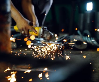
Grinding is the dividing line between AGMA 10 and AGMA 12+ work: continuous generating grinding (Reishauer, Kapp, Liebherr) hits AGMA 12–13 at module 2–6 in a 60–90 s cycle per gear; profile grinding is used for bevel gears where the tooth form is non-involute; honing and superfinishing of flanks (Ra < 0.2 µm) is reserved for wind-turbine and aerospace gearboxes where micropitting life is the constraint [S4][S5].
A procurement team that does not ask for a measured Ra value on the flank is buying to a print, not to a performance requirement [S4].
Stage 6 — Assembly, Lubrication, and Loaded Test Stand Validation
Assembly is where most warranty failures actually originate: bearing preload on the planetary carrier, gear-mesh pattern (checked with Prussian blue or automated bevel-gear rolling testers), and oil-flush cleanliness below ISO 4406 18/16/13 for splash-lubricated units and 16/14/11 for forced-circulation units [S4]. Each assembled gearbox is run on a no-load spin stand for 20–30 min to verify vibration, oil-temperature rise, and seal leakage before it is coupled to a loaded back-to-back test rig.
A supplier that cannot show you a back-to-back test cell with calibrated torque transducer (cross-checked on a multifunction process calibrator traceable to national standards), vibration spectral capture, and oil-temperature trend logs is a job shop, not a gearbox manufacturer — and that distinction is the single biggest predictor of failure rate in the first 12 months [S2][S4].
For buyers writing a sourcing RFQ in mid-2026, two signals are worth tracking: ask every bidder for the AGMA/DIN class they will hold on the supplied drawing (not the class they can reach on a sample), and require a process-capability index Cpk ≥ 1.33 on tooth-lead and run-out. Suppliers quoting AGMA 12 at industrial prices should be asked for a grinding-machine list and a throughput certificate, not just a brochure [S4][S5].